The ignition CDI boxes (two of them) have both failed on my Moto Guzzi V65. New ones are not available - I can get aftermarket replacements for a price but I think it might be fun to try to build my own.
I'm sure I'll have more questions along the way but my first is this:
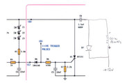
On all possible circuits I have found online, the output of the CDI module is wired to the positive side of the coil (see links 1 and 2 below). On all motorbike wiring diagrams I have seen the module output is connected to the negative side of the coil. The wiring diagram for my own bike shows it wired to the negative side of the coil - and it is! (See link 3 below). I don't remember seeing any vehicle - car or bike - that has the coil controlled from the positive side. I want to keep my wiring original as much as possible and don't really want to swap coil polarities, so how do I make these work to control the negative side of the coil?
https://www.homemade-circuits.com/how-to-make-capacitive-discharge/
https://www.homemade-circuits.com/dc-cdi-circuit-for-motorcycles/
https://www.thisoldtractor.com/guzzi007/schematics/1986_V65_Florida.gif
I'm sure I'll have more questions along the way but my first is this:
On all possible circuits I have found online, the output of the CDI module is wired to the positive side of the coil (see links 1 and 2 below). On all motorbike wiring diagrams I have seen the module output is connected to the negative side of the coil. The wiring diagram for my own bike shows it wired to the negative side of the coil - and it is! (See link 3 below). I don't remember seeing any vehicle - car or bike - that has the coil controlled from the positive side. I want to keep my wiring original as much as possible and don't really want to swap coil polarities, so how do I make these work to control the negative side of the coil?
https://www.homemade-circuits.com/how-to-make-capacitive-discharge/
https://www.homemade-circuits.com/dc-cdi-circuit-for-motorcycles/
https://www.thisoldtractor.com/guzzi007/schematics/1986_V65_Florida.gif