littletransistor
New Member
hey there,
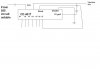
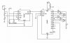
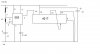
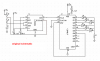
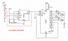
I'm trying to construct a running lights system, and hooked the 555 astable into the input (CLK) of CD4017, and let the rest do the job by connecting it according to the requirements in the datasheet.
However, I bumped into a problem... first - I'm making a 6-LED one, so I connected the 7th output into the Reset. Then, only a few LED are running, where outputs 0, 1, 2 and 6 are there. The 3, 4, 5 refused to lit up no matter how much I have reconnected it.
What could be the problem, the breadboard or the CD4017 chip?