Continue to Site

Welcome to our site!

Electro Tech is an online community (with over 170,000 members) who enjoy talking about and building electronic circuits, projects and gadgets. To participate you need to register. Registration is free. Click here to register now.

  • Welcome to our site! Electro Tech is an online community (with over 170,000 members) who enjoy talking about and building electronic circuits, projects and gadgets. To participate you need to register. Registration is free. Click here to register now.

Cascode BJT circut

Status
Not open for further replies.

electricslim

New Member
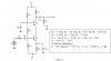
hello, i am new to electronics and i am having trouble trying to calculate the mid-band voltage gain vo/vi and the lower and uppper -3 dB frequencies for this circuit, when i do the small signal para's and use the ac model, i cant get any reasonable values to come out.

i figure out the q-points to be
Vce1 = 4.6V Ic1 = 1.011mA
Vce2 = 4.98V Ic2 = 1.0043mA
 

Attachments

  • cascode.JPG
    cascode.JPG
    79.9 KB · Views: 2,670
Midband gain is 200

Lower cut off is 1.06Hz. Upper cut off is 909MHz.

How close is that?

Your Q points are similar to what I have.

Please let me know

Thanks
I think your midband gain is too high.
Av≈(Rc||RL)/re1, where re1≈.026/Ie1. Ignoring the small attenuation caused by Rs, this comes out to be about 128.

I don't know what Cπ and Cµ represent. Your 909MHz upper cutoff frequency would require that Ccb2≈53femptofarads. That ain't gonna happen.:D
 
Last edited:
I got my midband voltage gain to be -128

I cant figure out how to do the lower and upper -3dB's, i am not sure what the equivalent circuit should look like, do i then just do the time constant method to find them?
 
I can find several references showing an equivalent circuit, such as:

Cascode - Wikipedia, the free encyclopedia

**broken link removed**

Some are for a FET cascode, but that's easy to change, and you will probably have to add a bypassed emitter resistor for the bottom transistor.

The equivalent circuit is not trivial to solve, but this is the 21st century, and you have computers to do the number crunching.

I get a mid-band voltage gain of 122.3, a low frequency corner at about 3460 Hz and a high frequency corner at about 17.88 MHz.
 
Last edited:
I agree that the midband gain should be nearer to 128. I forgot to include the ac coupled load in parallel with the collector resistor. I also used 25/Ic(mA) for the emiiter resistor.

I assumed Cpi and Cu were collector-base capacitance and base-emitter capacitance respectively.

The cascode circuit is designed for high frequency use. The collector-base capacitance of the transistor slugs the frequency response of most transistor circuit as it adds negative feedback (from the collector to the base) as frequency increases. The cascode circuit holds either the collector or the base at a constant voltage so this problem is not encountered. The top transistor has its base held constant. The bottom transistor has its collector held constant. The gain is produced by the collector load of the top transistor (in parallel with the load) and the Rbe of the bottom transistor
 
I can find several references showing an equivalent circuit, such as:

Cascode - Wikipedia, the free encyclopedia

**broken link removed**

Some are for a FET cascode, but that's easy to change, and you will probably have to add a bypassed emitter resistor for the bottom transistor.

The equivalent circuit is not trivial to solve, but this is the 21st century, and you have computers to do the number crunching.

I get a mid-band voltage gain of 122.3, a low frequency corner at about 3460 Hz and a high frequency corner at about 17.88 MHz.

How did you get the low and high frequency, the link tot the lecture notes you supplied is not working form me :(
 
Status
Not open for further replies.

Latest threads

Back
Top