Electro Tech is an online community (with over 170,000 members) who enjoy talking about and building electronic circuits, projects and gadgets. To participate you need to register. Registration is free. Click here to register now.
Welcome to our site! Electro Tech is an online community (with over 170,000 members) who enjoy talking about and building electronic circuits, projects and gadgets. To participate you need to register. Registration is free. Click here to register now.
Hi Suraj,
The Serial A and B are the data inputs to the shift regs.
Either A or B can be used as a 'gating' input in order to control the data input to the S/R.
example: If 'A' is high then data is entered via the 'B' serial input, if 'A' is low, then any data on 'B' will not be shifted into the S/R.
And vice versa, if 'B' is the high gate, then 'A' is the data input.
Note: if you change the state of the gating pin it clears the Qa output.
Eric to shift the bit it needs a CLOCK, but to change the state of the current bit it needs the A & B inputs state am I right?
The 'A or B' input is used as a gating signal for the other serial input.
Let 'B' be low for example, then as the S/R is CLOCKED, whatever the state of 'A' the data pin, it dosnt get clocked into the S/R, as the low on 'B' has inhibited the data bit from being clocked in.
If now 'B' is high, whenever the S/R is CLOCKED, the state of the 'A' pin is shifted into the S/R.
I'm wondering why it needs two inputs (A & B) to change the state? One is more than enough. It dosnt need two input to change the state, BUT one of the inputs has to be high in order the DATA on the other serial input to be CLOCKED in.Ex:A = HIGH the output will be HIGH
A = LOW the output will be LOW
Totally understood.Same as for A input.If 'A' is high, whenever the S/R is CLOCKED, the state of the 'B' pin is shifted into the S/R.
The 'A or B' input is used as a gating signal for the other serial input.
Let 'B' be low for example, then as the S/R is CLOCKED, whatever the state of 'A' the data pin, it dosnt get clocked into the S/R, as the low on 'B' has inhibited the data bit from being clocked in.
hi Sarma,
The problem you are describing is classic 'switch bounce'.
The mechanical switch will give multiple CLOCK pulses.
You MUST debounce the switch output before it inputs to the S/R/
The problem you are describing is classic 'switch bounce'.
The mechanical switch will give multiple CLOCK pulses.
You MUST debounce the switch output before it inputs to the S/R/
Is it ok if I place a cap between the SW? or better give clock from another IC.
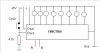
Eric is it ok my diagram I'm floating the 'A' input.& tie the 'B' input to Vdd.
Is there any serial data input time? I mean to make 'B' input high do I need to make it high all the time? or just a high pulse & keep it floating & make clocks will it work like that?
Hi Eric after denouncing will it shift nicely? It should be OK.
Is it ok if I place a cap between the SW? or better give clock from another IC.
Eric is it ok my diagram I'm floating the 'A' input.& tie the 'B' input to Vdd. Dont float the SERIAL DATA input, if you want to clock in '1s' tie it high or low if you want to clock in '0s'
Is there any serial data input time? I mean to make 'B' input high do I need to make it high all the time? or just a high pulse & keep it floating & make clocks will it work like that?
Hi Eric thanks for the useful diagram.It will be all right after debouncing the SW.
I see when giving inputs from micro controller they have tied both serial inputs together to a micro controller pin.And the clock pin to another micro controller pin.
In this case first I'll set the serial inputs (Both) pins to high & give the clock pulse to clock pin & see.
I hope the outputs wont latch.After working with a one S/R I'll try to combine another one to that to make 16 outputs.
This site uses cookies to help personalise content, tailor your experience and to keep you logged in if you register.
By continuing to use this site, you are consenting to our use of cookies.

")