Electro Tech is an online community (with over 170,000 members) who enjoy talking about and building electronic circuits, projects and gadgets. To participate you need to register. Registration is free. Click here to register now.
Welcome to our site! Electro Tech is an online community (with over 170,000 members) who enjoy talking about and building electronic circuits, projects and gadgets. To participate you need to register. Registration is free. Click here to register now.
Hi.
I am trying to cascade three 4017 counters inorder to light 27 leds and have them constantly run. I have found WEB sites on one 4017 but nothing on how to cascade them. I am using a 555 timer for the clock pulse.
Thanks;
William
Hi jbeng.
I made a mistake on the count of LEDs I only need 25.
So using four chips is no problem for me but I'll need some help.
also answering Allvols question I am trying to make a light sequencer or light chaser.
Thanks
William
Hi jbeng.
I made a mistake on the count of LEDs I only need 25.
So using four chips is no problem for me but I'll need some help.
also answering Allvols question I am trying to make a light sequencer or light chaser.
Thanks
William
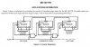
Here's a circuit that will do the trick.
From the first 4017 you use outputs "0" to "8", from the second
4017 you use outputs "1" to "8" and from the third 4017 you use
ouputs "1" to "9" to drive the leds. That's a total of 26 leds. If
you only need 25 outputs, use outputs "1" to "8" from the last
4017 to drive the leds and move the 1 nF capacitor which is
connected to output "0" to output "9". Connect each led with a
suitable resistor in series from each output to ground.
When either U1 or U2 = 5, the counter is reset rapidly.
U2 is advanced when U1/0 goes high.
I have not included a "power on" reset.
Therefore, since the counters will start in random states when the power is turned on, it may take a few clock pulses before the normal sequence starts.
If you can't buy a 74HC4022 or 74HC4017, let me know and I'll show you how to do it with a 4017, but it will require an extra IC since the 4017 may not have enough current source capability to drive the LEDs.
Choose resistors R0 ~ R4 for the correct LED brightness. For red LEDs, about 470 Ohm should be adequate.
Choose R & C according to the oscillator frequency that you want.
I would make R = 1M and choose C for the frequency you want.
The formula is f = 0.56/(RC) approx. (very approx)
With a 9V battery, the output current from an ordinary 4017 is about 12ma. A current-limiting resistor is not needed for the LEDs. When the battery drops to 6V then the LEDs will appear dimmer.
The absolute max continuous current allowed from the output of a 74HCxx IC is 25mA which looks only slightly brighter than 12mA, a regulated 5V supply is needed and a current-limiting resistor is needed.
Here's the way On Semi (Motorola) shows how to wire it. It's the section from page 6 of the mc14017b pdf file on their website. Using this method you could have a thousand led outputs if you want.
JB
*edit* Also, the entire setup can be reset from one pin by adding an OR gate into the reset line on the first (leftmost) counter.
I actually designed this circuit a couple of months ago, it was originally
intended to replace an obsolete IC in an antique calculator.
( The 1820-1223 cathode driver in an old hp 35 calculator.)
I had never tested this circuit because I was waiting for the description
and the schematic of this calculator but your circuit was so similar to my
original design that I decided to add an extra 4017 and build it.
Altough the circuit worked fine the addition of the third 4017 caused some
problems. ( The second and the third 4017 did exactly the same !) So I had
to add an extra gate to make it work the way it should, this extra gate was
made from the two 1N4148's and the 10k resistor. At this stage I should have
taken it back to the drawing board but I was too busy designing and testing
other circuits. But the circuit works fine the way it is so we'll add two or
even more 4017's.
The far left part is the first counting section and the far right is the last.
The one in the middle is the one you should duplicate a number of times to
drive the amount of leds you want, the more the better.
Have much fun !
This site uses cookies to help personalise content, tailor your experience and to keep you logged in if you register.
By continuing to use this site, you are consenting to our use of cookies.