Hello everyone,
I am a totally n00b when it comes to electronics, so bare with me.
I have a Buick LeSabre that has automatic temperature control. It's about 10 degrees out right now, and the blower fan works intermittently. The blower fan is ok, as well as the relay switch - it's something to do with the electronics.
Well, I don't like the automatic temperature control anyway, so I am going to directly wire the blower motor up.
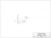
Here is my diagram:
**broken link removed**
First off, I don't fully understand how pulse width modulators or relays work. From my research, this is what it seems like I needed.
I know that the blower motor is 12v, and current relay that is hooked up to it is 30amps. I don't think I can use the current relay - a fellow buick owner said that:
SUMMARY
I am trying to directly wire my 12v blower motor to my car battery, and provide variable speeds. I am totally open to other ideas, this was just my initial concept.
Here is the pulse width modulator I was going to buy: **broken link removed**
Thanks for any help anyone can provide
I am a totally n00b when it comes to electronics, so bare with me.
I have a Buick LeSabre that has automatic temperature control. It's about 10 degrees out right now, and the blower fan works intermittently. The blower fan is ok, as well as the relay switch - it's something to do with the electronics.
Well, I don't like the automatic temperature control anyway, so I am going to directly wire the blower motor up.
Here is my diagram:
**broken link removed**
First off, I don't fully understand how pulse width modulators or relays work. From my research, this is what it seems like I needed.
I know that the blower motor is 12v, and current relay that is hooked up to it is 30amps. I don't think I can use the current relay - a fellow buick owner said that:
When the dash switch is moved to highest speed the first relay moves to a different contact. This disconnects the resistor set from the circuit and connects to the direct connection. Then a second relay allows the direct connect high speed relay to connect to the blower motor.
SUMMARY
I am trying to directly wire my 12v blower motor to my car battery, and provide variable speeds. I am totally open to other ideas, this was just my initial concept.
Here is the pulse width modulator I was going to buy: **broken link removed**
Thanks for any help anyone can provide
")