Continue to Site

Welcome to our site!

Electro Tech is an online community (with over 170,000 members) who enjoy talking about and building electronic circuits, projects and gadgets. To participate you need to register. Registration is free. Click here to register now.

  • Welcome to our site! Electro Tech is an online community (with over 170,000 members) who enjoy talking about and building electronic circuits, projects and gadgets. To participate you need to register. Registration is free. Click here to register now.

Capacitor Driven Solenoid; Please review my circuit

Status
Not open for further replies.

Cobalt60

New Member
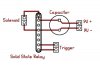
The purpose of this circuit is to drive a solenoid using a capacitor and a 9V battery. The 9V battery alone would not be capable of driving the solenoid, so the circuit should charge the capacitor, and fire the solenoid when the trigger is pressed.

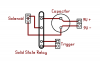
Attached I have a schematic I have made which I think is proper, but am not 100% sure. I am interested in knowing if I am charging the capacitor properly, and if I am grounding the solenoid properly. Of course, if you have any further advice it is appreciated.

I am not sure if this information is relevant, but the trigger will be on a 33% duty cycle and operating the circuit at up to 20Hz.

Thank you

-Chris P
 

Attachments

  • Dump1.jpg
    Dump1.jpg
    56.8 KB · Views: 361
What is the resistance of the solenoid?
What is the rated voltage of the solenoid?
 
Not exactly sure on the specs. If I connect an ammeter to the 2 terminals of the solenoid, I get a reading of 1.0 ohms. As for the voltage rating, I would say about 9 or 10V, as in their original purpose they were also driven by a 9V battery and a 10V 6800uf capacitor.
 
Something wrong with the 1Ω reading?

If it really where 1Ω at 9V, then the solenoid would require E^2/R = 9^2/1 = 81W.

I'm guessing more like 2-3W.
 
The easy way is to just power the solenoid with 9 volts and read the amps.

From there you can use ohms law to work out all other values.

9v / amps = resistance

9v x amps = watts

Why 20hz? is this some sort of flow control valve, like used in a hydralic system.

Do you have a better schematic of the controlling circuit.

Pete.
 
I have 2 different, but similar, of these solenoids. My bench supply only goes a little over 5A. Applying 9V to either of these solenoids clearly drew well over 5A. The lowest voltage these solenoids would actuate at was 3V, where they just barely didn't max out my power supply, drawing a little over 5A.

3V / 5A gives 0.6 ohms. Even though I originally stated 1 ohm, they are now both testing at about 0.7 ohms. If my math is correct, that's close to 13A, and about 115W.
 
What if I added an astable 555 set to 3ms between the trigger and the SSR? Please correct me if Im wrong, but I think that should lower the load on the battery. And also, does a 13A 3ms burst seem like it would be enough to operate such a solenoid? The travel of the solenoid is about 5mm.

Thanks very much for bringing this to my attention.
 
Wow, pretty sure my diagram is way off. Looks like the SSR is doing nothing in that circuit. Ill have to fix that when I get out of work.
 
Will this one work? I realize I still need to work a few things out in the trigger circuit, but is at least this part of the circuit correct? Thanks again.
 

Attachments

  • Dump2.png
    Dump2.png
    3 KB · Views: 342
Last edited:
Mate, you just put 4 posts that tell us 2/5 of F...all to your question.

My crystal ball was purchased from China and has intermitting faults, so you need to throw us a bone, and tell us what it is this thing needs to do, and what it is you require it to operate.

The figures you have quoted says it will work for about 5 minutes and then the battery will be flat.

If you give details then we can offer options, if not than this is a loss cause.

Pete
 
Status
Not open for further replies.

Latest threads

Back
Top