hello all,
Ive came across a circuit that interests me and although it looks awfully simple some of the components i do not fully understand why they are there. if anyone can explain the parts i dont understand that would be great.
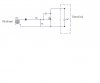
Basically the circuit is designed to discharge a capacitor quickly. The input is from a PWM switching at a high frequency. Now the parts that i am interested in knowing what their function is are the 10k and 100 ohm resistors.
I assume the 100 ohm resistor is your common low value resistor on mosfet inputs to prevent oscillation and to act like a low pass filter. The 10k resistor is a mystory to me? Also the capacitor i think its acting like a charge pump of some kind. to hold the mosfet on longer than normal? The transformer is to provide isolation. Also what is the diode doing, protection from back emf of transformer?
Thank you
Andy
Ive came across a circuit that interests me and although it looks awfully simple some of the components i do not fully understand why they are there. if anyone can explain the parts i dont understand that would be great.
Basically the circuit is designed to discharge a capacitor quickly. The input is from a PWM switching at a high frequency. Now the parts that i am interested in knowing what their function is are the 10k and 100 ohm resistors.
I assume the 100 ohm resistor is your common low value resistor on mosfet inputs to prevent oscillation and to act like a low pass filter. The 10k resistor is a mystory to me? Also the capacitor i think its acting like a charge pump of some kind. to hold the mosfet on longer than normal? The transformer is to provide isolation. Also what is the diode doing, protection from back emf of transformer?
Thank you
Andy
Attachments
Last edited:
