daviddoria
New Member
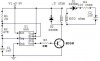
guys, i had another thread where we came up with :
http://bandtank.com/charge5.jpg
however, i built it and it didn't work . nothing happens at all when i turn it on. any tips on where to start trouble shooting??
http://bandtank.com/charge5.jpg
however, i built it and it didn't work
. nothing happens at all when i turn it on. any tips on where to start trouble shooting??