Continue to Site

Welcome to our site!

Electro Tech is an online community (with over 170,000 members) who enjoy talking about and building electronic circuits, projects and gadgets. To participate you need to register. Registration is free. Click here to register now.

  • Welcome to our site! Electro Tech is an online community (with over 170,000 members) who enjoy talking about and building electronic circuits, projects and gadgets. To participate you need to register. Registration is free. Click here to register now.

Capacitor Charge/Discharge question

Status
Not open for further replies.

ThermalRunaway

New Member
Hi everyone,

Please see the attached file for reference to a question I've recently been given as part of a test.

The question involves a capacitor charging from a supply at the changeover of a switch and I would normally find this kind of question very easy - you just use the formula VC = VS . 1- e-t/rc and transpose if you need any of the other variables (taking natural logs of both sides if necessary)

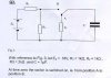
However, this particular question has confused me because you've got a capacitor charding via a fixed potential divider circuit. With the values given, this means that the capacitor can only charge to a maximum of 9V, because when fully charged the capacitor will be an open circuit and at that time the output of the potential divider will be 9V... right?

The first part of the question asks what the initial current will be. Well, if we're assuming that the capacitor starts off completely discharged, then initially it will be a short circuit so the current would be the supply voltage (18V) divided by the resistance of R1. Negligable current would flow through R2 due to the short circuit of the capacitor.

And this is where I start becoming confused. As the capacitor charges up, it will become more and more resistive. But then it's in parallel with R2, and I was unsure how this would effect the formula I originally quoted. The rest of the question goes on to ask how long it'd take to charge to a particular voltage, what voltage would be across the cap after a certain period of time etc but I'm guessing you can't use that formula anymore? If you can, what do you put for R in the equation?!?!?!

If only he had left out R2, I'd have flown that question.

Brian
 

Attachments

  • CapacitorCharging004.jpg
    CapacitorCharging004.jpg
    19.7 KB · Views: 696
It is a question of transient analysis...

I do not recollect the formulae right now... But once you switch on the cap,

There is a short transient respose and later there is a sustained steady state.

So do not look at the circuit from DC point of view.

Added later...
You can consider the cap short to being with.
charging with the time constant R1 C

later a resonance condition is to be considered of R2||C

and teh steadt state is when C is charged to a potential equal to Es x R2/(R1+R2) ... I think...
 
Last edited:
Thanks for the response. I would agree with your comments, and infact I'm not confused on those matters. I understand that the initial condition would be for the capacitor to be short circuit, and I understand that the steady-state condition would be for the capacitor to be an open circuit with it charged to the output of the potential divider (or close to it)

My confusion surrounds what happens in between these two extremes. It's no longer as simple as using VC = VS . 1- e-t/rc because the charging resistor is no longer a constant, it changes as the resistance of the capacitor changes because the cap is in parallel with R2.

Brian
 
The in-between condition is the transient state... I do not recollect the formulae.


But the graph of current versus time shall take the form of a damped oscillation. and finally be a DC line.

The in between state is that of the damped oscillation or the transient state. and the DC state is the steady state.

Sorry for not being able to help you further. I am not good at remembering complicated (even the simple ones) differential equations such as the one which represent the inbetween transient state.
 
ThermalRunaway said:
My confusion surrounds what happens in between these two extremes. It's no longer as simple as using VC = VS . 1- e-t/rc because the charging resistor is no longer a constant, it changes as the resistance of the capacitor changes because the cap is in parallel with R2.

Do you think that Thevenin's theorem might help finding the solution? Vs, R1, R2 can be replaced with an equivalent voltage source Veq with an equivalent series resistor Req. You might see if the equivalent circuit leads to sensible results.

Also, the similator might be a great help.
 
lord loh. said:
But the graph of current versus time shall take the form of a damped oscillation. and finally be a DC line.

I disagree with this comment. A graph of current versus time would show an initial peak current decaying until finally no current was flowing at all. Unless of course you're talking about the small current which would flow through the potential divider circuit?

Brian
 
hi brian,

Consider the resistance R1 as the source impedance of the voltage source.

Use Thevenin's theorem to solve the problem, the voltage rise across the Cap will be exponential. [which I suspect you already know].
 
Eric, Eng1.

Hmmm, I think you're right. R1 could be considered the internal resistance of the battery, although it's a very high value. In any case, I guess you could determine the equivalent circuit and answer the question that way.

Thevenin's theorem it is, then. Pity I couldn't have thought of that during the test!!!

Thanks all,

Brian
 
hi brian,
A final thought, why dont you construct the circuit, you have the values, use a CRO??... It will prove the result.
Eric
 
ThermalRunaway said:
I disagree with this comment. A graph of current versus time would show an initial peak current decaying until finally no current was flowing at all. Unless of course you're talking about the small current which would flow through the potential divider circuit?

Brian

Sorry... I guess I worded my thoughts wrong. That is what I meant.

And I think you need a real good CRO to to transient analysis - a storage one.
 
lord loh. said:
The in-between condition is the transient state... I do not recollect the formulae.


But the graph of current versus time shall take the form of a damped oscillation. and finally be a DC line.

The in between state is that of the damped oscillation or the transient state. and the DC state is the steady state.

Sorry for not being able to help you further. I am not good at remembering complicated (even the simple ones) differential equations such as the one which represent the inbetween transient state.
In the absence of inductance, there is no resonance.
 
Simply take the Laplace transform, solve the circuit with appropriate IC and take the inverse. Its the blind mathematical way to do it.
 
lord loh. said:
Sorry Ron H, I do not follow. How do RC Oscillators like the wein's bridge, Phase Shift and Colpitt's work?
Sorry, I should have said that in a passive circuit (no amplifiers), there can be no resonance in the absence of inductance.
 
My guess is that Vth is 9v, Rth of 500 ohm, so tau will be 500 micro seconds, thus full charge of 9v at 2.5 milliseconds.

It would be good to build and measure....
 
Ron H said:
Sorry, I should have said that in a passive circuit (no amplifiers), there can be no resonance in the absence of inductance.

I guess the inductor, in practical cases has some losses and needs soem energy to be fed into the tank circuit to compensate these losses. So I believe that there is no way to create an osicllator without an amplifier. Tell me if I am wrong.

Do you mean sustained oscillation when you say resonance? or do you count transient responses as well?

Now that 3iMaJ, mentioned the Laplace Transform, I am recollecting a few things. :eek:
 
FRIED said:
For the time constant, R1 is in parallel with R2 so TC = .5mS

R1 is not in parallel with R2, it is in series with R2. However, once the capacitor becomes resistive, it is then in parallel with R2 which means the "R" variable in the equation is no longer a constant.

Brian
 
Status
Not open for further replies.

New Articles From Microcontroller Tips

Back
Top