Continue to Site

Welcome to our site!

Electro Tech is an online community (with over 170,000 members) who enjoy talking about and building electronic circuits, projects and gadgets. To participate you need to register. Registration is free. Click here to register now.

  • Welcome to our site! Electro Tech is an online community (with over 170,000 members) who enjoy talking about and building electronic circuits, projects and gadgets. To participate you need to register. Registration is free. Click here to register now.

Capacitance question

Status
Not open for further replies.

3v0

Coop Build Coordinator
Forum Supporter
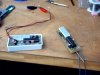
I am in the process of laying out a new PCB for the Mondo Superprobe. I have been attaching the tip/needle to the PCB by soldering it to a 10x20mm foil area on the board.

Will this corrupt readings? I am thinking that the foil would act less like a capacitor if there were no ground plain on the other side of the board. Is that good enough or do you think I should epoxy the needle to the board and do away with the 10x20mm foil?

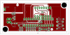
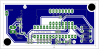
EDIT: I have added png's of the top and bottom. This is my first attempt at this layout and there will be problems so do not try to build from it. I will be increasing isolate.
 

Attachments

  • superprobe5_top.png
    superprobe5_top.png
    187.9 KB · Views: 211
  • superprobe5_bottom.png
    superprobe5_bottom.png
    192.7 KB · Views: 202
Last edited:
Capacitance is a few pF. Shouldn't make a big difference. I would minimize the area of the probe mount pad, but keep the ground plane under it.

To reduce stray signals on the probe node, however, I would move the probe trace to the red layer and extend the blue ground plane all the way under the whole length of the probe signal. You might have to reduce the separation rules from 'signal' to 'dimension' to get the continuity.

I would also move the power line on the red layer upwards, so you can get a continuous ground trace on the red layer inside of pins 1 thru 8.
 
On second thought, better than moving the probe line to the red layer, just make sure that the ground plane in red is complete on the outside of the resistors. This can be done by relaxing the signal to dimension rule.
 
On second thought, better than moving the probe line to the red layer, just make sure that the ground plane in red is complete on the outside of the resistors. This can be done by relaxing the signal to dimension rule.
Thanks. I was able to move the resistors closer to the processor and with a bit of work I now have everything you mentioned and a non broken ground around the edge of both layers.
 
hi 3v0,

Is fitting a single pin socket on the pcb an option.?

It would be then possible to plug in various types of pin probes, with tips to suit the job in hand.
 
hi 3v0,

Is fitting a single pin socket on the pcb an option.?

It would be then possible to plug in various types of pin probes, with tips to suit the job in hand.
That sounds like a good idea. Maybe change the needle out for a wire when working on a solderless breadboard.

But it would have to be a decent socket. Not sure the needle would fit without ruining the socket contacts etc etc..
 
That sounds like a good idea. Maybe change the needle out for a wire when working on a solderless breadboard.

But it would have to be a decent socket. Not sure the needle would fit without ruining the socket contacts etc etc..

If you have the resources, you could solder a threaded bush onto the pcb and make up a range of threaded probes.:)

I find the tips with the square recess that just fits an ic leg ideal for ic probing, none slip.!
 
If you have the resources, you could solder a threaded bush onto the pcb and make up a range of threaded probes.:)

I find the tips with the square recess that just fits an ic leg ideal for ic probing, none slip.!

I want to make at least six of these in the next few weeks so the kids have them when school starts. The tip I have been using is a common needle (tapestry maybe) that the SO located for me. It has a point that can be used with a solderless breadboard.

This is a great tool for what it is. Some day.... I would like to build a better version. Go to a larger PIC to get more pins to work with. Better LC. Do something about the voltage measurement limitation. Switch to a LCD with text instead of the cryptic 7 seg words.

The long probe in the attachment it the version that I have been using for over a year. The one in the box is the first prototype for the one I am working on. It is a SS board but I have switched to DS because I needed to move the display and switches to the bottom.
 

Attachments

  • twoRevs.jpg
    twoRevs.jpg
    60.8 KB · Views: 143
Last edited:
I havent tried it myself, but I would have thought some of those surgical hypo needles, with the threaded end, come in different diameters and are pointed.
 
I havent tried it myself, but I would have thought some of those surgical hypo needles, with the threaded end, come in different diameters and are pointed.
One would have to try them. The Needle I am using works well enough for now. You posted while I was editing my previous post. I added a image that will give you some idea of the scale. The prototype does not have a needle mounted.
 
Seen the image.

I looked at this tester when it came up on the forum a few weeeks ago, interesting spec.
Sadly I have no requirement for it.:(
 
Status
Not open for further replies.

Latest threads

New Articles From Microcontroller Tips

Back
Top