Continue to Site

Welcome to our site!

Electro Tech is an online community (with over 170,000 members) who enjoy talking about and building electronic circuits, projects and gadgets. To participate you need to register. Registration is free. Click here to register now.

  • Welcome to our site! Electro Tech is an online community (with over 170,000 members) who enjoy talking about and building electronic circuits, projects and gadgets. To participate you need to register. Registration is free. Click here to register now.

Capacitance Calculations

Status
Not open for further replies.
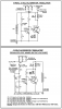
For the most part that is true. However I have been doing it for a long time now and have not had any problems with the GM 10, and 12 SI alternators in the original factory condition. As for the post above. I was trying to hint at the winding melting due to amperage and the severe heating of the unit at 100 volts. The mechanical stress is a factor, but only with the larger 15 SI, and 27 SI units as they have a physically larger rotor. Now for a engineering question? To tap the phases for AC would the above work that I posted? How best would this connection be made on a unit connected delta? For the Y connected units I am under the impression that tapping the center of the y connection would be a bad idea as it would hurt the overall efficiency of the unit?

Robert
 
You go before the diode connections, but what are you going to do with high frequency AC.
 
Are your 100 volt conversions overheating with a load or without one?

If you are running your rotor at 100% duty cycle with a 12 - 15 volts input it will get very hot all by itself. Most of the Delco 10 & 12SI alternators I have ever worked on or modified had a rotor winding resistance of around 4 - 5 ohms. At a 12 - 15 volts input that equates to as much as 60 watts of heat being built up in it all by itself and unfortunately by the design of most alternators the rotor itself sees the least amount of cooling effects.

As far as physical stresses go unless you are running the 10/12 SI units at 20,000+ RPMs and the bigger ones at 15,000+ RPMs I would have serious doubts about any negative physical stress issues on the rotor itself.
Over tight belts, or over long belts dancing around, would do more harm than anything and that is still limited to the bearings unless the alternator is poorly secured by what ever mounting methods you used.
 
RCinFLA, I want to use the AC to run the CFL and LED bulbs since the 100 watt bulbs are now outlawed in the US since Jan 1. Also some of the nickrome wire heating elements do not like DC while the older wire wound ones work fine on DC. AC for lighting and resistive loads, DC for brushed motor loads.


tcmtech. The conversion heat up the minute the switch is thrown and the engine started. Then the load only heats them up alittle more. Any suggestions on how to over come this issue?

Robert
 
Last edited:
Got a schematic of the setup?
How is the rotor being powered?
Alternator RPM's at no load?
How hot is hot?

If the stator windings are heating up without any load on them and its not from diode shoot through you have something someplace causing an internal short in the windings themselves. At no load with the diodes disconnected energizing the rotor to 12+ volts while the alternator is spin up to full speed should not produce mechanical load change if the alternator is good.

If it does power is being lost some place and it should become quickly obvious by what heats up. If the stator coils burn up they have a short. If the stator core heats up its got severe internal losses from bad material choice or more likely shorted laminations from rust or other magnetically induced parasitic loss issues. Either way a good alternator should not show looses from anything but windage when no electrical load is present if the rotor is being externally powered.

As far as temp rise goes a good alternator can run at up around 350+ F internal temps at full load in a engine compartment and not burn up.
 
I do have a schematic of the whole setup, but it would be impossible to share since it is part of a book by a commerical enterprise. I would have to draw my own schematic of the entire system so as not to violate any copyright laws by sharing the original. I do have just a hand drawn schematic of the inside of the converter box with the switch if you could tell anything from that? The rotor is simply full fielded from the battery when the switch is in the 110 volt mode. I do not know the exact RPM? I can tell you this much. The engine I have is an old briggs engine built to run at 1750 RPM for low speed tractor service. The engine is a 5 1/2 HP engine that is well over 30 years old. I have a 6 1/2 pully on the engine, and the standard stock pulley on the alternator. The engine has been fined tuned and barely makes it to 105 volts open at full throttle. Under load the voltage drops to around 91 volts with a 40 watt lightbulb. How hot is hot? Well I can't touch the thing without getting burned on my fingers. Pretty darn hot. I do know the laminations are peeling, and the windings are black from 31 years of use. The alternator was picked up from a yard sale decades ago and put to work and has never had a rebuild. The information I have found suggest the unit is 31 years old. I only converted it for 110 volts last winter as I know the alternator is got problems and figured it was good unit to try it out on. That is when I found out the windings were black and there was alot of rust in the unit. I cleaned it up and finger nail polished the bare spots in the windings and put it back together. The alternator does not get hot while charging batteries. Only when the switch is thrown and the 105 volts is generated. This setup is almost identical to what I have done with my alternator https://www.electro-tech-online.com/custompdfs/2012/01/When_is_110V_not_Over_Voltage.pdf If this is anymore help.

Robert
 
Last edited:
So you are running a crappy 30+ year old alternator that clearly shows signs of overheating damage and abuse and that does not raise any suspicions as to why its not working properly or efficiently?

30 years ago alternator diodes were far from what we see today in regards to breakdown voltage. Back then most where lucky to see 50 -80 volts PIV before they started working like big zener diodes.
I have a number of newer Leese Neville alternators that I have done diode tests on that showed zero breakdown even when high potted at a 1000 volts with my high voltage megger. The few Ford, Chrysler, and Chevy vehicle take offs I have done have taken the 250 volt high pot tests without fail but I don't think they ever made it much higher.

As far as 30 year old alternator diodes I have no clue but any alternators that I have came across that were likely to be that old or just as cooked looking as yours got stripped for the copper aluminum and iron without question.

I suggest taking $15 to the nearest scrap yard and get yourself a newer alternator from something preferably like a big Leese Neville from a commercial truck or bus, then try the experiments again. You may be surprised at what you get with good one of those in a modified design!

I love the the Delco 10SI and 12SI units for retrofitting to tractors and older vehicles but for AE work they have quite a bit to be desired.

As far as running with a 6.5 inch pulley on an 1800 RPM engine and a alternator pully that is likely around 2 inch in dia you are getting a roughly 5800 RPM alternator speed which is well within its stock working RPM range.

According to the specs sheets that the new Delco alternators that I put on tractors and what not say they are tested for output at 3600 RPM. The last one I bought was rated at 14.4 volts 76 amps at 3600 RPM although on a car it may see 20,000 RPM at the engine redline and still be expected to work properly even though it only had a 3600 RPM test speed rating.
 
I realize perfectly well that the age and condition of the alternator is most of the problem. Like a said, I used this alternator for testing the possibility of producing that kind of voltage from automotive alternators. Now that I know it works I am converting a $10 investment in a delco CS130 105 Amp unit. The conversion consist of replacing the useless voltage regulator since it cannot be isolated, as well as replacing the avalanche diodes with 50 amp bridge rectifiers rated for 1000 volts. Using bridge rectifiers increases the number of diodes from 6 to 12 which should better be able to cope with the higher voltages being developed. I am currently working with a fellow Len Cox to develope a voltage regulator more suited for this kind of work. Progress is being made, and sometime in the near future I will have replaced the old tired 63 amp delco.

My original point of this topic was to look into the possibility of using capacitors. I now see that it is impossible to obtain a large enough cap much less interface it with the alternator and it's voltage regulator. Now I will look into a new alternator and see what the results are with a newer alternator.


Now I have one more question for you? Since the rotor does not need the full power of the battery would it be possible to connect a large wire wound resistor or sand block resistor in line with the field circuit. The resistor would not be in the circuit when the 4 pole double throw switch is in the 12 volt mode. Only when the switch is switched bypassing the regulator and full fielding the rotor. Something like 10 ohm 5 watt since the field does not draw more than 6 amps. I am also considering adding a diode in line with the field for protection of the regulator.

Robert
 
Last edited:
One possibility is to use the stock regulator but power it from the external power source and use a simple resistor voltage divider network to drop the sensing input voltage down to a usable 12 volt level from the 100+ VDC output.

On the Delco SI series alternators there is a internal power feed from three phases to the regulator. It looks like a single block of plastic with three leads going to the three phase connection of the rectifiers and the fourth lead going to one stud on the regulator.

If you remove that it will allow an external 12 - 15 volt source to feed the rotor power through the F lead on the regulator wiring harness and the second S lead to work as a remote voltage sensing input point.
By putting a proper resistor divider on that input you can recalibrate the regulator to work with a different output voltage range.

To further complicate things you can also take a stock 5 - 10 amp universal power supply with a 90 - 250 volt AC input and 12 - 14 volt output and connect it to your 100+ volt DC output and use that to provide power to keep your battery charged.
 
One possibility is to use the stock regulator but power it from the external power source and use a simple resistor voltage divider network to drop the sensing input voltage down to a usable 12 volt level from the 100+ VDC output.

On the Delco SI series alternators there is a internal power feed from three phases to the regulator. It looks like a single block of plastic with three leads going to the three phase connection of the rectifiers and the fourth lead going to one stud on the regulator. If you remove that it will allow an external 12 - 15 volt source to feed the rotor power through the F lead on the regulator wiring harness and the second S lead to work as a remote voltage sensing input point.
By putting a proper resistor divider on that input you can recalibrate the regulator to work with a different output voltage range.

To further complicate things you can also take a stock 5 - 10 amp universal power supply with a 90 - 250 volt AC input and 12 - 14 volt output and connect it to your 100+ volt DC output and use that to provide power to keep your battery charged.
Such a power supply would have to be a switch mode type. A simple 10 amp switch mode battery charger from black and decker would work for this. The battery should operate the 110 volt mode for most of the day without serious drainage even without the battery charger.


Robert
 
Last edited:
One possibility is to use the stock regulator but power it from the external power source and use a simple resistor voltage divider network to drop the sensing input voltage down to a usable 12 volt level from the 100+ VDC output.
The attachment shows a similar arrangement, but it uses a resistive divider & a Zener diode.

The problem with a simple resistive divider is that it attenuates both the voltage & the voltage change.

Thus the changes seen by the Regulator (assuming a 100 Volt output from the alternator) are about 1/10th of the actual change that occurs at the 100 Volt end.

But by using a Zener, the Zener provides the off set for the voltage, but its dynamic resistance is low, so the voltage changes are not attenuated.

Note that - there is a drafting error in the lower diagram since the 1k resistor goes to the bottom of the coil, not the top as in the upper diagram.
 

Attachments

  • Reg-Sch-1.png
    Reg-Sch-1.png
    13.7 KB · Views: 239
Last edited:
Status
Not open for further replies.

New Articles From Microcontroller Tips

Back
Top