Electro Tech is an online community (with over 170,000 members) who enjoy talking about and building electronic circuits, projects and gadgets. To participate you need to register. Registration is free. Click here to register now.
Welcome to our site! Electro Tech is an online community (with over 170,000 members) who enjoy talking about and building electronic circuits, projects and gadgets. To participate you need to register. Registration is free. Click here to register now.
Propably 2200nF (the third 2=00).
The tone control circuit equivalent to German Dada-ism! That did not last either.
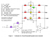
Simulate it before you waste time building it!
E
Your thought's on something different to try would be appreciated, basically I have tried the typical tone stacks of guitar amps but I want to try something different & lack ideas.
l: Some (most) sounds for guitar are not acheived with tone controls. You have to, in your head, identify what you want to hear or be heard. Most sounds are technique, not EQ. E
Yes, to a point I agree with that but the amplifiers need tone controls, some guitars & or amps are to bright others are flat & numb sounding so EQ is very necessary.
Most live bands etc sound like crap but thier CD's etc sound ok due to massive studio editing.
Having an amp with no tone controls would be like having a stereo without tone controls, if this were the case we would more than likely have the old AM radio sound or the old very numb valve amp sounds.
A lot of the old & much copied tone controls have seen better years so some new ideas are not going to hurt anything.
The guitar player can use their individual technique to colour the output sound from the guitars themselves but if the amps etc are not up to it then bad quality sound is the result.
A lot of people think in their head they have good sound or can play like Carlos Santana etc but in reality they need to have a closer look at themselves.
Or be told the honest truth, you only have to look at television shows like Idol to realise their are a lot of people with their head up their you know what.
They don't need tone controls but a baseball bat may help.
Good EQ for any man made sound devices is necessary, so why not strive for the best?
I have been simulating the Blaxandall 3 band EQ posted by audioguru above with good looking results.
Is it possible to add a Presence control to this EQ, I am not totally sure how the Presence actually works besides it appears to work from negative feedback from the amp?
Another question, what signal amplitude should be used for the input of this EQ to work at it's best (at the output pin of the first opamp), or doesn't this really matter?
Is it possible to add a Presence control to this EQ, I am not totally sure how the Presence actually works besides it appears to work from negative feedback from the amp?
This tone controls circuit has negative feedback.
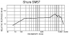
Presence is a boost to upper midrange frequencies. The legendary shure SM57 dynamic mic has a resonant peak at 6500hz to make a bright sound with presence. You can add a fourth frequency range to the 3-way tone control circuit to make a presence control.
Another question, what signal amplitude should be used for the input of this EQ to work at it's best (at the output pin of the first opamp), or doesn't this really matter?
The tone controls circuit works with line level signals (100mV to 700mV) because it has no voltage gain. The first opamp is important since its very low output impedance is required to drive the tone controls circuit.
As you would have guessed already, I have some more questions.
I mentioned I was simulating the circuit but that is only so good.
What formula's are required to be able to estimate-calculate the bandwidths for each band.
An example would be helpful.
What test setup & proccedure do I need to be able to view the frequency response of these as well, I want to try to view things myself on the O-scope to get a better understanding besides the simulation programs.
I want to have a more of a hands on approach but i'm not sure how to go about it correctly.
The 3-way tone controls circuit is extremely simple so the low filter is just a simple lowpass and the highs filter is just a simple highpass. The mid frequency filter is a very simple bandpass with gradual slopes. Simply reduce the values of the capacitors in the mid-frequency filter until they make a very simple (poor performance) presence boost.
The very wide bandwidth of the midrange filter and the gradual slopes of the lowpass and highpass filters are fine for a 3-way tone controls circuit. Adding a presence filter requires the original filters to have a narrower bandpass so that the frequencies filtered by the presence filter fit.
Then the filters need to be re-designed more like a narrow band equalizer circuit.
The multiple feedback bandpass filter usually has a very narrow bandpass so that a lot of filters can cover the entire hearing range of 20Hz to 20,000Hz. The resistor ratios determine the Q which is the bandwidth and amount of peaking.
Here is a good article about the filter and some examples: **broken link removed**
This site uses cookies to help personalise content, tailor your experience and to keep you logged in if you register.
By continuing to use this site, you are consenting to our use of cookies.