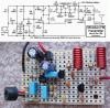
I've purchased the components to build this:
**broken link removed**
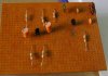
And I can't seem to tune into a frequency in the lower 88mhz area or any other. I did it on a big breadboard to make it clearer as the first attempt failed as well.
What can else can I try to debug the problem? I'm a novice in elecronics.
Thanks.
**broken link removed**
And I can't seem to tune into a frequency in the lower 88mhz area or any other. I did it on a big breadboard to make it clearer as the first attempt failed as well.
What can else can I try to debug the problem? I'm a novice in elecronics.
Thanks.
")