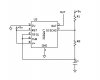
I have a 555 IC set up in astable mode with R1=100KΩ, R2=1MΩ, and C1=1uF on a breadboard powered by a 9V battery.
This gives me roughly 1.4Hz which is fine. I've actually reused this particular breadboard/555IC setup to power rough clock cycles for a few projects, but it suddenly stopped working. I figured I had accidentally pulled a wire or something, but I've rebuilt it 10 times now, replaced the wires, replaced the IC, replaced the capacitor, measured the resistors, and I just can't get it to work properly again.
When I connect power to the circuit the output on pin 3 turns on the resistor/LED combo that I have on pin 3 briefly, but then stays off instead of cycling. When I disconnect and reconnect the power, same symptoms. With the power attached I measure a 9V drop between the two leads of R1. Does that make any sense? R2 has almost no drop.
I'm at a loss. How else can I troubleshoot/measure this to figure out why it's not working?
I can post a photo/schematic if it would help, but it can't get more basic. I'm not using a capacitor on pin 5 but I don't think that matters. Certainly didn't before.
Last edited: