Continue to Site

Welcome to our site!

Electro Tech is an online community (with over 170,000 members) who enjoy talking about and building electronic circuits, projects and gadgets. To participate you need to register. Registration is free. Click here to register now.

  • Welcome to our site! Electro Tech is an online community (with over 170,000 members) who enjoy talking about and building electronic circuits, projects and gadgets. To participate you need to register. Registration is free. Click here to register now.

Can two timers make a repeat cycle timer?

Status
Not open for further replies.

tiktaalik

New Member
Hi all

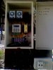
I found this picture on one forum. The original poster said the system is used to control a solenoid valve for sprinklers in repeat cycle manner, i.e. on for a set time and off for another set time and repeat on and so on.

Unfortunately the poster said it does not work correctly. My question is can we connect two timers as shown in the picture to make a repeat cycle(twin timer).
If not, how to make it works.

My guess is that the left timer is a countdown timer with solenoid valve(and so the transformer) connected to NO. When the system starts, the vale is on for a set period of time then the timer switch to NC. NC pin feeds the right timer and start a countdown "off" time. When the right timer off time is reached it switch off the line that feed the left timer.

But then I don't know how the left timer would start again , so can this possibly works?

Any idea?

Mick
 

Attachments

  • R8684715-1.jpg
    R8684715-1.jpg
    60.9 KB · Views: 449
  • R8684715-46.jpg
    R8684715-46.jpg
    61.3 KB · Views: 368
  • R8684715-53.jpg
    R8684715-53.jpg
    65.3 KB · Views: 434
At the risk of asking an obvious question, why not just buy a sprinkler timer?
 
Thanks Carl
I'm asking the same question too why not use a repeat cycle timer, as I do. May be it's hard to find in the area. May be the guy just don't buy stuff from internet. I don't know. But just for curiosity sake. Can any one answer ?
 
Looks like an expensive and complicated way of doing something cheap and simple to me!
 
Actually the circuit seems to have 3 timers.

If I read the drawing correctly it should resemble the attached drawing. It should work. When the main timer (I called it that for want of a better term) NO contacts closes Timer 1 will begin a delay on make timing process through the NC contacts of Timer 2. Following a programmed delay Timer 1 contacts 1 & 3 will close applying power to Timer 2 beginning Timer 2 delay on make. Additionally Timer 1 contacts 8 & 5 will close providing mains power to Transformer T1. Things will remain in this state with T1 powered until Timer 2 completes its delay on make. Once Timer 2 times in the NC contacts of Timer 2 (4 & 1) will open removing power from Timer 1. When this happens, Timer 1 contacts 1 & 3 as well as 8 & 5 will return to their NO states and things will remain that way till the Main Timer contacts open and then close again when the cycle will repeat itself.
If I got the drawing correct (a big “if”) I believe that is how it should work. Transformer T1 will be energized for the timing duration of Timer 2 delay on make.

**broken link removed**

Anyway, that is how I think it should work. The only reason I see for the timer I call Main Timer is so the process can be set to take place at a time of day and easily reset. Yes, there are simpler ways to go about this but whatever. I am really guessing on my explanation but "think" that is what is goingt on.

Ron
 

Attachments

  • Relay Timers.jpg
    Relay Timers.jpg
    63.7 KB · Views: 648
About the main timer

Thanks Ron.

So you said the Main timer is the one that reset the cycle? My guess is that the main timer is for controlling time period that the the cycle will apply. For example it turn On at 9 in the morning and off at 5.30. During the time, the sprinklers go on for 2 minutes and of for 5 minutes in cycle.

But from your diagram. May be the system could work. I figure It just need another one shot relay to reset the 1st timer. Any Idea how?

Mick
 
Looking at the circuit as I drew it, and I am only guessing I got it correct, I see it this way. When the main timer contact close, Timer 1 will begin its delay based on what it is set for, at this point nothing is happening. Following the preset delay timer 1 contacts that are normally open will close. Two things will happen, power will be applied to the transformer and timer 2 will be started for its programmed delay. Once timer 2 reaches its programmed delay then the timer 2 normally closed contacts that are powering timer 1 will open. The problem is things seem to stop there until the main timer contacts open and then close again to reset everything. I am just missing something in all this.

Also, I am not sure I read the picture correctly as to the circuit and what it should look like. The way this should work is when the main timer contacts close you want timer 1 and timer 2 to alternate on and off so you would water for whatever like 30 min and off for 15 min then on for 30 min as long as the main timer was energized providing power. You want timer 1 and 2 to toggle.

Later today if I have time I’ll mess with it. I have done timing like this at work but it has been awhile.

Ron
 
Status
Not open for further replies.

Latest threads

New Articles From Microcontroller Tips

Back
Top