Andy1845c
Active Member
Just want to make sure I know what I am doing before I soldier")
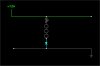
I want to wire 80 strings of leds between a 12volt supply and a ground rail like this.
The data sheet for the LEDs can be found here: https://www.electro-tech-online.com/custompdfs/2006/12/tfe30uyc.pdf
Forward Voltage is 2.3 typ. Max current is 70ma.
Is this correct? 12v - 9.2v = 2.8v 2.8v/56ma = 5hm:
Would 56ma be a safe current for continious operation?
Is there any reason my circuit won't work or will shorten the life of the LEDs?
Note: the 3 circles in the diagram are supposed to be LEDs. the applet I drew it in shows them weird until rolled over with the mouse.
I want to wire 80 strings of leds between a 12volt supply and a ground rail like this.
The data sheet for the LEDs can be found here: https://www.electro-tech-online.com/custompdfs/2006/12/tfe30uyc.pdf
Forward Voltage is 2.3 typ. Max current is 70ma.
Is this correct? 12v - 9.2v = 2.8v 2.8v/56ma = 5
hm:Would 56ma be a safe current for continious operation?
Is there any reason my circuit won't work or will shorten the life of the LEDs?
Note: the 3 circles in the diagram are supposed to be LEDs. the applet I drew it in shows them weird until rolled over with the mouse.
Attachments
Last edited: