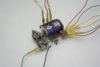
Based on my second link to that blog, they say they were originally designed for AC voltages, around 12V to 18V. Some say you can also pulse it with DC 12V. This is momentary only, the switch latches in position and stays there until the other coil is energized to move it back to the other latched position. You cannot leave the power on the coil all the time, it will likely overheat. All the other wires (6 of them) were used to turn on indicators or help switch track voltages on/off (based on position of switch turnout).
Not sure about the two front wires in the picture. They seem extra on some switches. It may be to create a temporary contact that disconnects the coil voltage when it is switched. That is, it is in series with the coil voltages, but on the opposite "pole". WHen a button is pressed, power goes thru the front switch to the coil. As the coil starts to "snap" to the other position, the contact breaks and moves to the other coil wire, ready for switching the other direction. This is a theory of mine, not a fact, but plausible.
Or that front switch is a more heavy duty switch and is designed to switch the rail power (the back contacts seem a bit small to switch O gauge rail power, which can be high). Back contacts are then only for switching signalling/indicators.
Image of datasheet shows top "switch" contacts connected to rails:
View attachment 124218