Continue to Site

Welcome to our site!

Electro Tech is an online community (with over 170,000 members) who enjoy talking about and building electronic circuits, projects and gadgets. To participate you need to register. Registration is free. Click here to register now.

  • Welcome to our site! Electro Tech is an online community (with over 170,000 members) who enjoy talking about and building electronic circuits, projects and gadgets. To participate you need to register. Registration is free. Click here to register now.

Can someone recommend a good mic preamp circuit?

Status
Not open for further replies.

crococo

New Member
I want to record sound (mostly speech) on my computer, but the mic input is too noisy. I've read that it would be better to connect the microphone to a preamp and then connect it to the line in of my sound card.

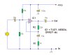
I found this circuit:
https://www.epanorama.net/circuits/micamp.html
but I've read somewhere that a circuit with more transistors is better(?).

Just some background info: I have only assembled a few circuits (I'm still studying) and I don't know how to design so I really need some help! Thanks!
 
Funnily enough I've just (1 hr ago) submitted an article with a mic pre-amp circuit! It should do what you want. Still awaiting its publication. Check under 'Circuits/Audio' in the next day or so.
Your mic is almost certainly of the electret type.
 
Funnily enough I've just (1 hr ago) submitted an article with a mic pre-amp circuit! It should do what you want. Still awaiting its publication. Check under 'Circuits/Audio' in the next day or so.
Your mic is almost certainly of the electret type.

Ok. I'll check it out. Thanks!
 
I don't see the mic preamp project here.
The article about the extremely simple mic preamp says "quite poor distortion performance figures, a little bit noisy".
I had the schematic of another very old but good preamp made with two transistors but it must be on the hard drive of my old broken computer.
Everybody uses an audio opamp as a mic preamp today. Since the headset mic is very close to the mouth then its gain does not need to be much. Can you design a simple opamp preamp?
 
I don't see the mic preamp project here.
Well the article is still 'unpublished', but the above link works for me (maybe because I have editing rights as author?)
 
Well it wasn't designed for that; just to boost the 'mic in' signal. I don't think the 'Line in' input provides any voltage to drive the amp. Does anyone out there have a schematic for the 'Line in' input of a typical PC sound card/chip?
 
here is an easy circuit.. Power supply to this circuit can be 12v or 18v.. U can Make your choise for ic1 and download its datasheet from net
 

Attachments

  • 3361935981_e007d1de80.jpg
    3361935981_e007d1de80.jpg
    34.3 KB · Views: 538
Last edited:
Hi Alec T,
I left a comment on your project's page that the schematic has the gain trimpot connected wrong.

Hi Ziddik,
1) Your preamp has no filtering for the biasing of the opamp so hum and noise on the power supply is amplified by the opamp.
2) The mic is not biased so it must be a dynamic type (coil and magnet) not the electret type used in the mic in headphones.
3) The output does not have a series 100 ohm resistor to isolate the output of the fast opamp from the capacitance of shielded cable so the opamp will probably oscillate at a high frequency.
 
I've googled around and got some info on line-level input voltages, impedances etc, so have designed this circuit :-
MicLineLevelPreamp.gif
In simulation it has a voltage gain of 200 (adjustable by varying R1 or R2), an input impedance of 10k, can drive into 10k (R3 is a test load and is probably redundant), and THD of 0.09 %.
U1 was selected as it can operate with a supply down to +-4V, is available in DIP form, and a model is included in LTSpice. Other ICs are doubtless suitable.
R6 provides the bias for an electret mic. R7 is to suppress oscillation as mentioned in AG's post #14.

@AG
Thanks for pointing that out. I'll look into re-designing that preamp at some stage, as the gain difference between the two modes isn't as great as I originally intended.
 
I've ..... so have designed this circuit:-
Your opamp circuit has a fairly low input impedance and the resistor R6 that powers the electret mic also has a low value. Then they will load down the mic and cut its output level in half which doubles the noise level. The opamp should be non-inverting so it can have an input impedance (including the biasing resistor) of 100k and the mic should be powered from a filter (1k resistor with 47uF to ground) then 10k to power the mic.
 
Thanks for your comments, AG.
You might need an input impedance of 100k if the electret mic was just a bare electret element. However, the (cheap) electret mic capsules I've played with have had a built-in FET, as I understand it, providing a low output impedance (<1k??), so driving a 10k load doesn't attenuate their signal much.
Bearing in mind there's an internal FET and that the supply to the mic is only 4.5V by virtue of R4 and R5, do you still think 4k7 is too low for R6?
Since the mic is battery powered and at the 'line in' socket is not taking power from the PC (as it would at the 'mic in' socket) is the filter justified?
 
Last edited:
....anyway, taking Audioguru's comments on board, here's a Mark 2 version. (N.b. the component numbering has been changed to improve the readability of the schematic). The op-amp is now non-inverting and the mic bias resistor is now 10k. An additional 47u decoupling cap has been added.
In simulation, input impedance is 100k (so should suit any flavour of mic module), voltage gain is 200, THD is 0.08 % .
MicLineLevelPreampMk2.gif
**broken link removed**
Edit: can post a .asc file if anyone wants to play with simulating this or variants.
 
Last edited:
Hi Alec T,
The Jfet in a two-wires electret mic does not have a 1k output impedance because it is common-source, not a source-follower. Its impedance is about 3.9k effectively in parallel with the 10k resistor that is its drain resistor. The total impedance is about 2.8k ohms.

In your preamp I added a filter for the power fed to the electret mic. Your new C3 should be removed since it couples power supply noise into the synthesized ground. I added a capacitor to filter the battery voltage.
Your gain is 221 which is too high for a headset mic that is almost touching the mouth. A gain of only 30 to 50 might be good.
 

Attachments

  • mic preamp.PNG
    mic preamp.PNG
    28.6 KB · Views: 326
Last edited:
@audioguru
Thanks for the explanation of the mic internals. I was somewhat in the dark there.
I'll go with the filter on the mic bias voltage and the gain required, but we're talking line level here, i.e. about 1V pk-to-pk; so is the required gain really as low as 40? If so, make R2 = 47k, or knock R3 down to 390k?
I don't see any difference in function (as distinct from value) between your new 100uF and my C3. Both are simply connected between V+ and the synthesised ground. Or would the 100uF be better connected between V+ and V- ?
You mention power supply noise. Is a 9V battery noisy? (Mea culpa: I omitted to mention that a PP3 was the intended power source).
 
Status
Not open for further replies.

Latest threads

Back
Top