Continue to Site

Welcome to our site!

Electro Tech is an online community (with over 170,000 members) who enjoy talking about and building electronic circuits, projects and gadgets. To participate you need to register. Registration is free. Click here to register now.

  • Welcome to our site! Electro Tech is an online community (with over 170,000 members) who enjoy talking about and building electronic circuits, projects and gadgets. To participate you need to register. Registration is free. Click here to register now.

Can anyone please confirm this is valid?

Status
Not open for further replies.

bigal_scorpio

Active Member
Hi to all,

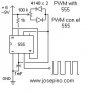
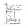
I was just hoping someone could verify this circuit.

It is designed to output PWM on pin 3, but having built it 3 times I am beginning to wonder if its OK, as I said I have made it 3 times on Veroboard all to no avail.

Thanks for looking............Al
 

Attachments

  • 555pwm.jpg
    555pwm.jpg
    9.7 KB · Views: 150
Last edited:
There is a mistake in the schematic. Here is the fixed version:
 

Attachments

  • 555pwm.jpg
    555pwm.jpg
    11.3 KB · Views: 144
Sorted!

Hi to both of you,

Thanks guys, thats got it cracked!

Now I can get on with the PWM project for She who must be obeyed! ;)

Thanks again..........Al :)
 
You're making your wife a PWM controller for her Iron for her Christmas Present ? ;)

Hi Picbits,

Hehehe, now thats an idea! ;)

But seriously she wanted some LED lighting in a glass fronted cabinet and couldn't make up her mind what colour she wanted, so I just made her an adjustable RGB one. Three pots and she can now have any colour she likes!

Now I can get back to my projects without that funny whining noise. hehehe

Al
 
Status
Not open for further replies.

New Articles From Microcontroller Tips

Back
Top