Continue to Site

Welcome to our site!

Electro Tech is an online community (with over 170,000 members) who enjoy talking about and building electronic circuits, projects and gadgets. To participate you need to register. Registration is free. Click here to register now.

  • Welcome to our site! Electro Tech is an online community (with over 170,000 members) who enjoy talking about and building electronic circuits, projects and gadgets. To participate you need to register. Registration is free. Click here to register now.

Can anyone help to identify this part ?

Status
Not open for further replies.

Swifty

New Member
A friend has given me his electronic speed controller from an RC model to have a look at as after a crash it stopped working..
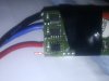
Upon opening it I can see that a component has come away from the board but unfortunately it's probably in the middle of the field where he crashed ;)

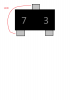
I'm not sure what the component is or does so wonder if anyone has any clues to help find replacement? there are two still left on the board above the area marked in the picture, all I can discern from the top of the chips is what looks like '7 - 3' ?!?

Any help would be greatly appreciated! :)
 

Attachments

  • IMG_20110226_183721.jpg
    IMG_20110226_183721.jpg
    785.3 KB · Views: 210
Thanks, thats a start :)
I'm guessing you spotted already but just incase, the component is actually connected to 3 pads - 2 at the bottom and 1 at the top.. but I presume you are referring to the bottom two pads being joined by the track on the board ? - (as you can probably tell, i'm not an expert at this sort of thing by any stretch of the imagination! :) )

Is there anything I can test with a multimeter or such on the components that are left to help figure out what I can replace this item with ?

Many Thanks

I would say thats a transistor, also I would guess all 3 in that row are the same type.
Is there type number printed on any of them.??
 
All that appears to be printed on the other two are what looks to be "7 3".. thats it, which I'm guessing isn't much help!?
 
All that appears to be printed on the other two are what looks to be "7 3".. thats it, which I'm guessing isn't much help!?

hi,
The image is not very clear.?

Is the copper track inside the red boxes, a continuous strip across those two pads.
 

Attachments

  • AAesp01.gif
    AAesp01.gif
    124.5 KB · Views: 180
Yes sorry, I don't have a decent camera to hand at the moment.

The track you marked is continuous between the two lower pads (just confirmed with multimeter)
The single pad above and to the center has no connection to either of the two lower pads, it is connected to the brownish component just above.

Cheers

hi,
In that case its possible that 'houseofwax' is correct it could be a dual diode.

I would carefully remove one of the other 'devices' and use a test meter to measure the resistance across all the pins, all combinations.

If you post what you measure we may be able to say what it is.
 
Ok, I only get a reading on one set of pins top center and bottom left, also I only get a reading when 'COM' on the DMM is connected to the top center pin, if I swap the probes around then I get nothing.

With the DMM set to '200K' I read around 127~120K, all other pins are showing nothing.
 

Attachments

  • Component.png
    Component.png
    32.7 KB · Views: 166
Aha! The markings on the component could indeed be Z 3 ! they are very faint so I could easily have misread the Z for a 7..

I just put my DMM on to the diode setting and tested across the top center and bottom left, it reads '431'.. it reads the same both ways (ie. if I switch the probes round) so not sure what that means!?

Certainly looks to be a good match visually going by the datasheet though
 
I guess that the 431 means 431 mV, which is a bit low but possible for the diode voltage drop. It would imply that the DMM tests at a very low current.

The fact that it is the same both ways means that there is some other diode in the circuit the other way round. That diode may be part of the protection circuit in one of the ICs.

The zeners that I have here read 0.652 V on the diode test when checked forwards, and open circuit in reverse. The zener voltage is larger than the maximum test voltage for my DMM, which is expected.
 
Hmm, you say because of the readings I got it means there is some other diode the other way around in the circuit, but I tested this unsoldered from the board..
Sorry if I've misunderstood what you meant?!
 
I did think that you had tested it in circuit. I have no idea why the meter would read the same both ways round when it measures the resistance as being different.

To test a zener, you put a 1k resistor in series with a 9 V battery, and measure the voltage after the resistor. That should read as follows:-
9 V. No connection or zener voltage more than 9 V
3 - 8 V. Zener the correct way round. You can read the zener voltage from the meter.
0.6 V. Zener the wrong way round.
 
Status
Not open for further replies.

Latest threads

New Articles From Microcontroller Tips

Back
Top