Electro Tech is an online community (with over 170,000 members) who enjoy talking about and building electronic circuits, projects and gadgets. To participate you need to register. Registration is free. Click here to register now.
Welcome to our site! Electro Tech is an online community (with over 170,000 members) who enjoy talking about and building electronic circuits, projects and gadgets. To participate you need to register. Registration is free. Click here to register now.
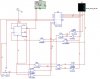
it is a school project. im asked to design a count limiting circuit based on 74ls193 4bit binary up and down counter.what i have posted is the limiting circuit and the counter.
it is a school project. im asked to design a count limiting circuit based on 74ls193 4bit binary up and down counter.what i have posted is the limiting circuit and the counter.
it is a school project. im asked to design a count limiting circuit based on 74ls193 4bit binary up and down counter.what i have posted is the limiting circuit and the counter.
it works. just sometimes the output is unexpected, and have to be reset. i also want to get rid of some gates for more convenience wiring,or maybe another better design.
it works. just sometimes the output is unexpected, and have to be reset. i also want to get rid of some gates for more convenience wiring,or maybe another better design.
I would suggest you look at the 'clear' pin for the initial '0' and the 'load' pin for restarting the count at '1'.
You are not using the full capabilites of the LS193.
hi, i have tried it out. it works perfectly fine on multisim simulation. can u check for me if there is anything i can improve? like adding a filter or something? thx!
hi, i have tried it out. it works perfectly fine on multisim simulation. can u check for me if there is anything i can improve? like adding a filter or something? thx!
hi,
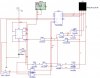
I see that gates U9A/U7A and U12A/U17A detect a '0' , then RESET F/F U13A.
Gates U9A/U7A and U3A/U4A detect a '9' and toggle the state of the F/F U13A.
Both of the above actions determine which clock pin on U2 is used ie: up/dn
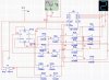
For the U13A power on CLEAR are you allowed to use diodes??? or must you use another gate.?
BTW: I would have detected the '8' state [D] to Clear the F/F and the '1' state of the LS193 to Set the F/F.
The Clear would have been combined with a power reset from a Res/Cap circuit.
This site uses cookies to help personalise content, tailor your experience and to keep you logged in if you register.
By continuing to use this site, you are consenting to our use of cookies.

")