Menticol
Active Member
Hello!
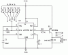
I've built a timer to trigger my cammera shutter at a fixed intervals. The camera switch was interfaced sucessfuly, and the circuit (done with a 555) worked well.
YouTube - Prueba de Camara 3
Today, I'm building the circuit again, the older one was lost
___________________________________________________________
I really hate the noobs who ask to get their homework done, but sadly I've converted in one of them because my empirical knowedge isn't enough. If you wanna give me a hand, please:
___________________________________________________________
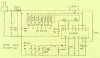
I tried changing values of the resistors, and attaching a riridulous ammount of capacitors, but I didn't reached the required intervals. Also tried with potenciometers.
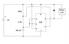
As my potenciometer approach failed, I liked the idea to use a rotary switch and a set of resistors (in place of the 100K resistor shown in the circuit) to set any of this four optional values: 5 min, 10 min, 30 min, one hour.
But I still can't get the correct resistor values, even with a regulated +5V supply, I get random times everytime. I know the 555 IC on this application tends to be inprecise, due temperature and components tolerance, but the random results are unnaceptable.
I admit I'm not using the mathematic formula, just trial-and-error. Or maybe the circuit I'm using (and the way I'm modifing it) is not suitable for the application.
Any feedback would be very appreciated.
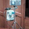
PS: I've attached a picture of the old setup, very ugly, the "tape casing" was because I ran out of time before sunrise)
I've built a timer to trigger my cammera shutter at a fixed intervals. The camera switch was interfaced sucessfuly, and the circuit (done with a 555) worked well.
YouTube - Prueba de Camara 3
Today, I'm building the circuit again, the older one was lost
___________________________________________________________
I really hate the noobs who ask to get their homework done, but sadly I've converted in one of them because my empirical knowedge isn't enough. If you wanna give me a hand, please:
___________________________________________________________
I tried changing values of the resistors, and attaching a riridulous ammount of capacitors, but I didn't reached the required intervals. Also tried with potenciometers.
As my potenciometer approach failed, I liked the idea to use a rotary switch and a set of resistors (in place of the 100K resistor shown in the circuit) to set any of this four optional values: 5 min, 10 min, 30 min, one hour.
But I still can't get the correct resistor values, even with a regulated +5V supply, I get random times everytime. I know the 555 IC on this application tends to be inprecise, due temperature and components tolerance, but the random results are unnaceptable.
I admit I'm not using the mathematic formula, just trial-and-error. Or maybe the circuit I'm using (and the way I'm modifing it) is not suitable for the application.
Any feedback would be very appreciated.
PS: I've attached a picture of the old setup, very ugly, the "tape casing" was because I ran out of time before sunrise)
Attachments
Last edited: