Electro Tech is an online community (with over 170,000 members) who enjoy talking about and building electronic circuits, projects and gadgets. To participate you need to register. Registration is free. Click here to register now.
Welcome to our site! Electro Tech is an online community (with over 170,000 members) who enjoy talking about and building electronic circuits, projects and gadgets. To participate you need to register. Registration is free. Click here to register now.
That pin just generates a test signal. A sine wave I think. And you clip your probe to it and see if the signal your oscilloscope is measuring is the one that it's supposed to be measuring.
Well, you need to attach the probe to that contact; it outputs a signal (typically a square wave) at a certain amplitude and frequency (check your manual). Set your scope controls for that amplitude and frequency (voltage/time-base), and see if it matches what your manual says. If it does, all good. If it doesn't - then you typically tweak various calibration controls on the scope front (generally recessed, and you might want to use non-conductive screwdrivers for the adjustment).
Most of the time, it will only need very minor adjustments, but if it is really off and the adjustment controls on the scope don't help, then you need to get it professionally calibrated by the manufacturer's service center (which may not be cheap); they have special calibration signal sources they use for this work, plus they can tweak interior controls and such (or I imagine for newer scopes they adjust things in software)...
And don't even think about doing it yourself - I looked into what it would cost for the calibrated signal source for one of my scopes after I got the service manual for it that gave calibration instructions - the cost for that source tool was INSANE - then I wondered about how much it would cost to get the calibrated signal source device calibrated...
Welcome to the wonderful world of scopes - nowadays, its probably almost cheaper to buy a new scope, than to get the old one calibrated...
The test signal is a squarewave, primarily for adjusting the compensation cap on a x10 scope probe. This ensures the probe is flat divide by 10 versus frequency. Typically 5vpp but not that accurate.
The test signal is a squarewave, primarily for adjusting the compensation cap on a x10 scope probe. This ensures the probe is flat divide by 10 versus frequency. Typically 5vpp but not that accurate.
To elaborate on that, you look at the square-wave on the 'scope and adjust the compensation cap adjustment screw on the 10X probe until the top of the square-wave is flat, with neither undershoot or overshoot at the leading edge of the waveform.
...and it can also be used to set various things (if you have the controls on the scope), such as focus, trace intensity, trace rotation, and such; I never stated it was for anything more beyond that, though I suppose I should have mentioned the probe compensation as well (as that is likely its primary purpose). It isn't perfect, but if its all you have to begin with, its a start. I would hazard to say that most of us don't own the necessary tools to properly and truly calibrate a scope; I know I looked for such tools for my scopes, and those tool cost 10-20x what I paid for my scopes (used), which was definitely not worth it. Though I am sure that some of us here do have access to such tools (I unfortunately don't).
To elaborate on that, you look at the square-wave on the 'scope and adjust the compensation cap adjustment screw on the 10X probe until the top of the square-wave is flat, with neither undershoot or overshoot at the leading edge of the waveform.
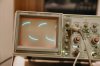
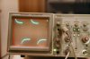
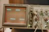
A few pictures are worth a thousand words. Below are a few images of an everyday Tek scope I use. The first image is a 10X probe connected to the scopes .5 V Pk to Pk 1 KHz square wave cal out followed by under compensated, over compensated and something like just right (actually called critical compensation if I remember correctly).
You cant tell if a scope probe is uncompensated using a sine wave (without sweeping a wide range of frequencies). The wave needs to have a fast rise/fall time.
Well it's not actually a flaw. The vertical input channels on all scopes have vertical input compensation internal to the scopes vertical input channels. During calibration they are adjusted so the scope displays input signals as they really are. The vertical inputs will frequently have the input characteristics listed right at the channels, typically like:
1MΩ
20 pF
No two scopes will have identical characteristics. For this reason when we add a 10X or 100X probe the probe needs to be compensated to the scope's vertical input channels. This is so the probe will display an incoming waveform accurately and what it really looks like.
The reason a square wave is used frequently is because a good 1 KHz square wave is easily produced and the leading edge of a square wave contains an infinite number of odd harmonics. Plenty of high frequencies.
As Mike points out a sine wave could be used but you would need to sweep across a wide range of frequencies maintaining a constant amplitude in from the source. Sort of much more difficult.
The image I posted for under compensated shows poor high frequency response. Called high frequency attenuation. The overcompensated is responding to the high frequencies but poor low frequency response. High frequency accentuation.
Thus, 10X and 100X probes have compensation adjustments on the probe so the probe can be compensated to the individual scope channel(s). These adjustments (tweaks) are on the probes.
<EDIT> Jim was quick while I slowly typed. < / EDIT>
This site uses cookies to help personalise content, tailor your experience and to keep you logged in if you register.
By continuing to use this site, you are consenting to our use of cookies.

")