Continue to Site

Welcome to our site!

Electro Tech is an online community (with over 170,000 members) who enjoy talking about and building electronic circuits, projects and gadgets. To participate you need to register. Registration is free. Click here to register now.

  • Welcome to our site! Electro Tech is an online community (with over 170,000 members) who enjoy talking about and building electronic circuits, projects and gadgets. To participate you need to register. Registration is free. Click here to register now.

Calculation on which resistor to use in a speaker circuit.

Status
Not open for further replies.

far1shta

New Member
Hello Electronics People

I have a tiny problem that i hope some of you can help me solve...
Currently i am making an electronics project at school, where i, among other things, have to make a speaker circuit
that makes a sound at 500Hz and a few other frequencies...
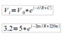
I would like to know how to calculate which resistor i should use, to make the right frequency..
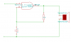
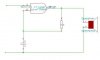
Ive added a picture of my diagram.
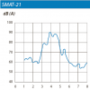
The schmitt trigger nand gate is a CD4093BE, the speaker is a sonitron - SMAT-21, and the capacitor is a 220uF.
Ive tried using a few different formulas, but i cant seem to hit the frequency that i want. I dont know if this has got anything to do with the delay of the nand gate, or the fact that i havent taken some data into my calculations.
For some reason i cant upload images to this forum so i have a link here instead.
**broken link removed**
Hope you can help me.

far1shta
 

Attachments

  • lydgiver.png
    lydgiver.png
    3.4 KB · Views: 261
  • lydgiver.jpg
    lydgiver.jpg
    11.8 KB · Views: 273
You are shorting the output of the Nand gate with the d.c. resistance of the speaker. Put a 100uF DC blocking capacitor (+ to gate) in series with the speaker. Also, the speaker impedance should be high, like 500 Ohms. If it is a low impedance speaker (4-35Ohms) that is too low for the Nand gate to drive.
 
The "speaker" in this case isn't quite a speaker as many of us think of a speaker but rather Piezo Element and the data sheet can be found here. I don't know that the best choice is the SMAT-21 since you mention 500 Hz. but I guess it will work.

I suggest you read this for some information explaining how your CD4093BE NAND Gate actually works as an oscillator. Focus on the "Oscillators" section of the link. You want 500 Hz, your capacitor is 220 uF but you fail to mention the important Vdd? Again, read the link and see where Vdd figures into things.

Ron
 
The piezo transducer is shown being driven push-pull by two CD4093 gates and other Cmos gates and inverters in its datasheet.
Its frequency response shows a peak at 4kHz and not much response below 3kHz or above 5khz. It is a whistle.
 

Attachments

  • piezo transducer.PNG
    piezo transducer.PNG
    11.2 KB · Views: 412
I can't help but wonder looking at the original post if the frequency shouldn't be 5 KHz and not 500 Hz? My thopughts when I first saw the "speaker" was a pizeo I thought that 500 Hz. seemed peculiar. Oh well, I guess we await the return of the OP to see what exactly they have in mind because I sure don't quite get it. :confused:

Ron
 
Vdd is 5V.
ive found out that the schmitt trigger triggers at 3.2V.

when i put in a 48k resistor i get a freq about 250Hz
 
Last edited:
Hi there,


I did a few experiments with another type of CMOS Schmitt trigger IC and found the following frequencies to occur with the respective parts:

200k 0.1uf 56.45Hz

100k 0.1uf 112.9Hz

100k 0.01uf 1125Hz

Notice that 100k 0.1uf is the same as 100k 0.01uf if you just multiply the frequency by the same factor as the capacitor? This suggests a
formula:

Freq=R*C/1.125

Also, increasing the voltage from 5v to 15v did not change the frequency except for a very very small amount.

One thing to keep in mind however is that the frequency may change over temperature. The trigger thresholds are all over
the place when the temperature changes over the full range. 'Course for driving a speaker or piezo it may not matter that
much. BTW there are speakers that have 100 ohms impedances rather than the typical 8.
 
BTW there are speakers that have 100 ohms impedances rather than the typical 8.
A CD4xxx Cmos IC can barely drive 2200 ohms and certainly not as low as 100 ohms. The piezo transducer's impedance is about 10k ohms.
 
I have tried to use this formula to find the right resistor... But i seem to get a negative resistance value, which means that i am doing something wrong.
 

Attachments

  • formler.png
    formler.png
    3.9 KB · Views: 154
Last edited:
Use the formula MrAl provided in his post. He even provided a few examples to work from.

Ron
 
When i use his example with my current values like a capacitor of 220nF and a resistor of 9k i get a frequence of 1.6mHz which is not correct...
When i make this setup i get a frequency of around 1kHz
 
Status
Not open for further replies.

Latest threads

New Articles From Microcontroller Tips

Back
Top