Continue to Site

Welcome to our site!

Electro Tech is an online community (with over 170,000 members) who enjoy talking about and building electronic circuits, projects and gadgets. To participate you need to register. Registration is free. Click here to register now.

  • Welcome to our site! Electro Tech is an online community (with over 170,000 members) who enjoy talking about and building electronic circuits, projects and gadgets. To participate you need to register. Registration is free. Click here to register now.

Calculating Wattage on resistors

Status
Not open for further replies.

McGuinn

New Member
Could someone verify my maths in this one...

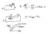
I have an air-cooled resistor which lies in series with a 55W lamp, and it's used to dip the lamp on a car when driving during the day. The car runs 12V DC.
It's resistance is 1.7 ohms, and the coil had burned out due to dampness and such.
My plan is to replace the wire wound unit with a standard high wattage resistor of a similar resistance.

My maths goes as follows:
The resistance of the 55W lamp is:
E^2/W
144/55 = 2.61818 ohms.

The combined resistance of the two components is 2.61818 + 1.7 = 4.3818 ohms.

This will dissapate the following watts in total:
E^2/R = W
144/4.3818 = 32.863 W.

The wattage per component is the ratio of the resistance:
(W/R)*R1 = R1W
(32.863/4.3818)*1.7 = 12.465W for the 1.7 ohm resistor.
(W/R)*R2 = R2W
(32.863/4.3818)*2.61818 = 19.1979W for the 2.61818 ohm light.

So that means I need a minimum wattage of a ~16W resistor.

Is my calculation of the wattage correct or am I making a mistake?
 
in a car E=14V not 12V and resistance of bulb light is a non-linear resistance...
I think a true mode to put a exactly aditional resistor is to make more experiment... live... to determine rezistance bulb light with voltage
 

Attachments

  • light.jpg
    light.jpg
    22.8 KB · Views: 650
Ok, thanks for your feedback.
I'll measure the voltage on the car (I think 13.4 is the accepted voltage when the engine is running) and I'll check the voltage drop across the two parts.
 
McGuinn said:
Ok, thanks for your feedback.
I'll measure the voltage on the car (I think 13.4 is the accepted voltage when the engine is running) and I'll check the voltage drop across the two parts.

13.8V is the nominal voltage for a car battery.

Have you considered getting a replacement resistor off of a scrap car in a scrapyard? - probably easier, and cheaper, than getting a suitably large wirewound - and it would plug directly in.

I don't know what sort of car you have, but my 1990 Vauxhall Astra had 'dim dip' headlamps, using a similar sounding resistor. Presumably pretty well any car with this system would use a similar value?.
 
Your mistake is in assuming that the lamp resistance is constant. In fact it is non linear (positive temperature coefficient) as niq_ro pointed out.

So the lamp has minimum resistance when it is cold, thus the current will be much higher initially. So the resistor has to withstand a higher power dissipation initially than when the lamp resistance has stabilised.

Len
 
Well hang on, I didn't measure the lamp resistance, I used it's wattage (55W) to calculate it. As the lamp is not produced by a single vendor, I am trying to compensate for small changes in resistance.

The reason for looking for a resistor based solution is because the cars (Alfa 145) are becoming rare, and while I could get one from a scrapper, I want to see if I can make a viable replacement to what Alfa fitted.
 
I think we've lost the plot here!.

You already know the value of the resistor - 1.7 ohm.

Where are you going to find a high wattage 1.7 ohm resistor?, except as a specific spare part.

Assuming you can find them, I would suggest you get a 25W one, as long as you mount it on a decent size heatsink. If you're not planning using a heatsink then go for a 50W or 75W one.
 
That's the thing... I can't find a 25W 1.7 ohm resistor, so I need to use a pair of 3.4 ohm ones in parallel. I need to know whether two 10W ones will be suitable....
 
McGuinn said:
That's the thing... I can't find a 25W 1.7 ohm resistor, so I need to use a pair of 3.4 ohm ones in parallel. I need to know whether two 10W ones will be suitable....

Try them and see! - but I would have thought they will probably run too hot. Assuming it's dissipating something like 16W, two 10W resistors will be running too near their maximum ratings and you probably won't be able to touch them , and they will probably melt insulation off wires.

Does your car use one for each light?, or one for the pair?. If it's one for each light then measure the voltage across the existing resistor when it's turned on
 
Those old meter shunts with the brass ends were sometimes around that value.
You can adjust their value a small amount by filing them narrower.
 
Does it have to be resistor?
I'd rather put small PWM circuit that would:
- run much cooler than series resistor
- have adjustment so you can set the brightness to whatever you choose.
There are so many very simple circuits and here is something just
to get you interested:
http://www.solorb.com/elect/solarcirc/pwm2/index.html
 
Status
Not open for further replies.

Latest threads

New Articles From Microcontroller Tips

Back
Top