Continue to Site

Welcome to our site!

Electro Tech is an online community (with over 170,000 members) who enjoy talking about and building electronic circuits, projects and gadgets. To participate you need to register. Registration is free. Click here to register now.

  • Welcome to our site! Electro Tech is an online community (with over 170,000 members) who enjoy talking about and building electronic circuits, projects and gadgets. To participate you need to register. Registration is free. Click here to register now.

calculate value of resistors in circuit

Status
Not open for further replies.

nachosavage

New Member
hey every one. ím new to electronics and to the forum.

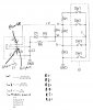
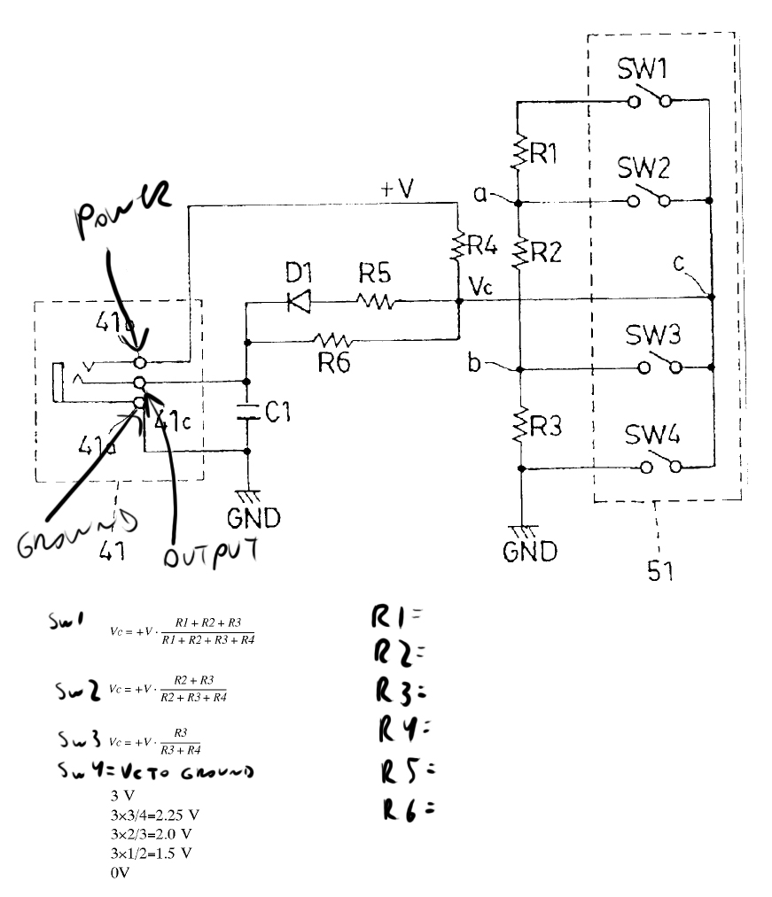
I need to find the value of the resistors in a circuit i need to replicate. I have the voltage input and output values. but i dont get how to use the ohms law in this case (sinse i dont have the resistostors value)

untitled-1-jpg.47841

can someone give me a hand?

thx in advance (and plz mind the poor english)
 

Attachments

  • Untitled-1.jpg
    Untitled-1.jpg
    179.5 KB · Views: 440
Hi,


Yeah i think a little more info would be a good idea.
Are you trying to generate five voltages 0, 1.5, 2.0, 2.25, and 3v or something else on the output?
Also, what is the diode needed for, and is it to be considered an ideal diode or real life diode?
Also, what is the input voltage?
Also, is there any load resistance to consider?
 
Last edited:
hey, guys.

i really dont have that many details, but i´ll try to elavorate.

i´m trying to replicate a piece of hardware thats missing from an electric drum module. I have the schematics for the circuit, but no values for the parts.

basically it has a 3v input, and if you press con the diferent switches, it divides the voltage to 3/4, 2/3, 1/2 or 0. dis changes are interpreted by the drum module thus produsing diferent sounds when you stricke a pad (like a drum hihat pedal)

so, i´m after the values of R1 to R6 in order to be able to build the circuit. i have limited electronics knowlege. so the formula it´s beynd my reach.

so now, anwering the questions

Are you trying to generate five voltages 0, 1.5, 2.0, 2.25, and 3v or something else on the output?
i´m trying to generate five voltages 0, 1.5, 2.0, 2.25, and 3v

Also, what is the diode needed for, and is it to be considered an ideal diode or real life diode?
it´s in the original schematic. I guess it has to do with the switches not been connected to the common ground.

Also, what is the input voltage?
3V

Also, is there any load resistance to consider?
no sure.
I measured the drum module output (its a trs conector that connects to the circuit trough a stereo cable) and I get.
R/T=60kΩ / -1.3volts
S/T=-90kΩ / 3.3volts
S/R=73kΩ / 0.05volts.

i hope this clear it up.

thx again.

greeings, Nacho.


Hello again,


I dont understand some of your notes, such as a negative value for the resistance.

What do you mean by R/T, S/T, etc. ?

Do you have any resistors around so that we could do a couple of well chosen tests to find out what we really need here?

Did you try connecting say a 50k resistor from the input to the output to see what kind of sound you got? The idea would be to test with a couple different value resistors to see what sound you get, then go from there.

Do you know for sure that the only function of this circuit is to generate different voltages, and not perhaps part of an oscillator circuit or something like that?
 
Last edited:
hey,
sinse you asked about tghe load resistance, i measured the piece of equipment that this circuit connects to.

its connected through a stere o rts cable. so I took measures of

Ring/Tip=60kΩ / -1.3volts
Sleve/Ttip=-90kΩ / 3.3volts
Sleve/Ring=73kΩ / 0.05volts.

Do you have any resistors around so that we could do a couple of well chosen tests to find out what we really need here?
Did you try connecting say a 50k resistor from the input to the output to see what kind of sound you got? The idea would be to test with a couple different value resistors to see what sound you get, then go from there.

I have some resistors and i´m trying to replicate the circuit in a breadboard. so far I got open and close hihat.

Do you know for sure that the only function of this circuit is to generate different voltages, and not perhaps part of an oscillator circuit or something like that? i´m sure it´s only voltage.

also, I think that the formulas shown, are some what of a clue. sinse it illustrate the difrents resistors that interact with the switches.
 
Hi again,


Ok, well resistance measurements are normally not negative, so im not sure what you mean by -90k ohms.

Here are a couple of tests you could start with:

Test1:
Leave D1 and R5 out for now.
Make R4 a 10k resistor.
Make R6 a 10k resistor.
Connect power and see what sound you get.

Test2:
In addition to the above Test1, connect a 50k pot from Vc to ground.
Vary the resistance of the pot and see what sounds you get.
 
Last edited:
Ok, well resistance measurements are normally not negative, so im not sure what you mean by -90k ohms.

The problem is that there is some voltage on the terminals where the resistance measurement was taken.
This will confuse the ohm meter no end!
The reading of -90kΩ is meaningless.

So are the other resistance measurements meaningless, as there is a voltage there also.

JimB
 
Status
Not open for further replies.

Latest threads

Back
Top