Continue to Site

Welcome to our site!

Electro Tech is an online community (with over 170,000 members) who enjoy talking about and building electronic circuits, projects and gadgets. To participate you need to register. Registration is free. Click here to register now.

  • Welcome to our site! Electro Tech is an online community (with over 170,000 members) who enjoy talking about and building electronic circuits, projects and gadgets. To participate you need to register. Registration is free. Click here to register now.

Calculate operating temperature in transformer?

Status
Not open for further replies.

Stenberg

New Member
Hello!

I need some help with how to calculate, I want to found out the thermal resistance of a transformer, in order to choose a suitable heatsink for natural cooling.

I assume that I need to find out the operating temperature in order to get the thermal resistance from using this equation:
Rth=delta T /(Pcore + P,cu,winding)

*My question is how do I calculate the operating temperature in this transformer?

I have chosen a transformer core ETD49/25/16 (3F3) and have calculated the core and winding losses. Core loss=4 W and the winding loss=7W, so total loss is 11W.

The area of the copper wire are: A,cu=1.7671 mm^2.
Np=15
Ns=14

The thermal resistance of copper are calculated as: Rthcu,wire=(Rth,cu*l)/A=(0.00250626*0.5mm)/211mm^2 = 5.939*10^-6 C/W
Where l is the air-gap between the copper wire and the core.
Rth,cu=1/(399 W/mC)

Thermal resistance of air:
Rth,air=26.7 mC/W

Thermal resistance of wire isolation:
Rth,isolation=6.5359 mC/W

Thermal resistance of core material ferrite:
Rth=8 C/W

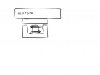
P.S. don't know if it helps, but have drawn a picture of the EI-core and the heatsink placement, the primary winding and the secondary winding are separated by using bobbin/isolation.

Thanks for any help!


//Stenberg
 

Attachments

  • EI-core.jpg
    EI-core.jpg
    39.6 KB · Views: 119
Get a 10watt resistor. Glue your heatsink onto the top of the resistor and increase the size of the heatsink until you feel the heatsink and say "that's just right."

I did a 6 year university degree to arrive at this solution. It cost me just $65,000. Great value !!!!
 
I have never seen a heat sink on a transformer.

----edited----
Usually the data sheet will give you the hot spot temperature of the core.

The thermal resistance to air for copper is much worse inside a transformer.
 
Last edited:
Have you considered that, since the wire is not evenly distributed over the core, some parts of the core will be hotter than others?
 
Hi, thanks for reply’s!

I have thought about that it is not evenly distributed. However, it seems difficult to get accurate results, so I have considered different ways to make an estimated temperature rise. (One way to try and simulate it, but I don’t have that much time left at this project.) So right now, I considered how to calculate the T_rise with an estimation formula I found, but that formula comes with the assumption that:

“One approach is to lump the winding losses together with the core losses and assume that the thermal energy is dissipated uniformly throughout the surface area of the core and winding assembly at all ambient temperatures. This isn't a bad assumption, because the majority of the trans-former's surface area is ferrite core area rather than winding area, and the thermal conductivity of ferrite (˜40 mW/cm/°C) is poor at any temperature.” **broken link removed**

From this formula I get T_rise to be 70.86 Celsius. With an estimated ambient temperature of 40 Celsius, the T_body becomes 110.87 Celsius. The core according to datasheet should maximum be 155 Celsius. Do I not need any cooling for the transformer?

But I have not considered the increase in temperature if it will operate for 6-9 hours, and don’t know how to. And, how to keep the ambient temperature as constant as possible in an enclosed box.

I could not find a hot spot temperature of the core from the datasheet. Datasheet: http://c1170156.r56.cf3.rackcdn.com/UK_PMA_ETD49_25_16-3F3_DS.pdf


//Stenberg
 
lump the winding losses together with the core losses
I think this is good. Think about a Toroidal, EE/EI, and a pot core/shielded core. It does not matter if the core heat must get through copper or if the copper heat must get through core to get out.
**broken link removed****broken link removed**
I try to keep the hottest part of the core below 100C.

It is a good balance to have the copper loss and the core loss to be about the same. If one is 1:10 then the transformer is not a good design.

Some cores talk about the temperature of "outside" verses "center leg" temperature.
 
Stick 2,3 or more pieces of temperature indicating tape on the outer surface and run for 1 hr.
Max.
 
It is fairly easy to measure the temperature rise withing a transformer or motor,by measuring the winding resistance when cold and again when hot.
Knowing the temperature coefficient of resistance for copper, you can calculate the rise in temperature above ambient.

The downside of this is that if you have a small winding with just a few turns of thick copper wire, the resistance will be very low to start with.

JimB
 
The problem with small transformers like this is (think it is already mentioned) that heat does not distribute evenly, and presumably gets hotter at the inner most windings because no air to cool and little or no contact with medium that can transfer the heat anywhere out.

Bigger transformers (those you typically find in power grids) are filled with oil to compensate for that issue. In your case however this is not a solution for you because heavily overload will probably cause core saturation and therefore less power effiency - and also if not correctly manufactured it may be dangerous to catch fire - and the transformer "package" may be dangerous to touch because the oil may conduct electicity too.

Maybe you can just put it into clean water if you want to operate with low voltages - never ever think about doing this is you're going to connect it to mains.
 
I use the winding resistance method that JimB mentioned. While it won't give the hotspot temperature, it does give the average winding temperature, and you can account for this by limiting the average internal temperature to a lower value than what the insulation is rated for. Here is a detailed method that I posted on another forum some time ago:
BobW said:
The DC resistance of the winding changes with temperature. For copper it's 0.0039 ohms/°C/°C. So, simply measure the primary winding resistance before powering up the transformer and also make note of the room temperature. We'll call this the cold resistance Rc and cold temperature Tc. Then run the transformer under load for a minimum of 1.5 hours, then disconnect power and measure the resistance again. We'll refer to this hot resistance as Rh. The internal temperature is then:

Th=Tc+Rh/(0.0039*Rc)-1/0.0039

(Regarding the 1.5 hour test, I've found that even very small transformers will need this long to reach thermal equilibrium, However, if you have an orphan transformer with no mfgr. data and don't have any idea of what the transformer's VA rating is, then you should begin with a very modest load and test the hot temperature every few minutes to be sure that it's not severely overloaded.)

For doing the test, it may be more convenient to determine in advance, the resistance value that corresponds to the maximum allowable design temperature. Let's say 90°. So, then it's simply a matter of making sure that the winding resistance doesn't exceed this value. The formula is:

Rh=Rc*(0.0039*(Th-Tc)+1)

So, let's say you measure the transformer primary at 20°C (room temperature), and get a value of 150 ohms. Applying the above formula, Rh comes out to be 191 ohms. So, as long as the hot resistance of the primary never exceeds 191 ohms you should be okay.

To put it even more simply:
The hot resistance of any transformer winding should never be more than 1.27 times the cold resistance.

I recommend measuring the primary winding resistance because its temperature rise will account for all losses, will usually be the inside winding which is most critical for temperature, and will generally have a resistance that's high enough to measure with reasonable accuracy.

If the transformer has multiple secondary windings, you can do the same test again, but measuring the secondary winding resistances, to find out their load limits.

I should also mention that 90°C is too hot to touch, and so you may consider that to be pushing things a bit too hard. However, this is referring to the internal temperature, not the surface temperature of the transformer, which should be considerably cooler. However, if the surface is ever too hot to touch, then I would consider it to be overloaded.
 
Are you talking about an EI transformer or a toroid transformer?

I use to work for a company that built transformers, I have the formulas to design & build continuous duty EI transformers.
 
Status
Not open for further replies.

New Articles From Microcontroller Tips

Back
Top