Continue to Site

Welcome to our site!

Electro Tech is an online community (with over 170,000 members) who enjoy talking about and building electronic circuits, projects and gadgets. To participate you need to register. Registration is free. Click here to register now.

  • Welcome to our site! Electro Tech is an online community (with over 170,000 members) who enjoy talking about and building electronic circuits, projects and gadgets. To participate you need to register. Registration is free. Click here to register now.

By window comparator works fine in sim but does not work in practice

Status
Not open for further replies.

EfeVural

New Member
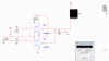
The circuit i attached is a window comparator it will it compares a given input with high and low referance voltages. And if is between them output is +vcc if not very low.. It works fine in simulation but when it comes to set up the circuit my seven segment lights everytime whatever my input voltage...Why? Please help me this is a part of my lab project and very little time left for demonstration.. Thank you for your help in advance :)
 

Attachments

  • wincomp.png
    wincomp.png
    25.4 KB · Views: 376
Your Sim works apparently because it does not accurately reflect what happens when you incorrectly connect devices together.

You can not connect the outputs of two such op amps in parallel as you have done (you can do that with some comparators that have an NPN transistor open collector output such as the LM339, but not op amps). These outputs need to go to an AND gate input.
 
I understand..

Let me clear the situation. I want to setup a circuit which produces output if it is equal to a referance voltage and produces not if it is not equal. How can i do?
 
also i have to use one ppwer supply one way to do this is to use a window comparator and take the outputs to a summing opamp but with one power supply it fails
 
To make an AND gate, connect a diode (two diodes total) to each op amp output (cathode to output). Connect the two diode anodes to a 1k ohm pull-up resistor. Connect the other end of the resistor to the plus supply. That way the diode output will be high only when both op amp outputs are high (when the node 3 voltage is between the node 5 and node 6 voltages).
 
god bless you man that is great help i dont know if there is +rep in this forum if there is please let me know i will give you one :D
 
Status
Not open for further replies.

New Articles From Microcontroller Tips

Back
Top