Continue to Site

Welcome to our site!

Electro Tech is an online community (with over 170,000 members) who enjoy talking about and building electronic circuits, projects and gadgets. To participate you need to register. Registration is free. Click here to register now.

  • Welcome to our site! Electro Tech is an online community (with over 170,000 members) who enjoy talking about and building electronic circuits, projects and gadgets. To participate you need to register. Registration is free. Click here to register now.

Busker amp problems help please

Status
Not open for further replies.

Angelic777

New Member
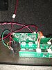
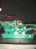
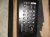
I have a Artec PMD 3-8 amp I connected the wrong power supply now it doesn't work
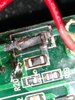
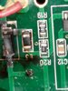
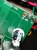
I can't see an internal fuse
So are these amps just fry and Finnish I mean I've got loads of power supplies all with the same plug
 
There doesn't seem to be a schematic available (on a quick google), which makes life difficult - however, there 'may' be a fuse, just that you can't recognise it - fuses come in a wide variety of different shapes and sizes, including surface mount ones, and ones that look like small transistors.

Try posing pictures of the board, we 'may' be able to identify something for you.
 
Can anyone see a type of fuse in this circuit
 

Attachments

  • IMG_20210325_131106318.jpg
    IMG_20210325_131106318.jpg
    4.9 MB · Views: 217
  • IMG_20210325_131112519.jpg
    IMG_20210325_131112519.jpg
    4.7 MB · Views: 188
This is the Artec PMD 3-8 20 watt three channel busker amp which has fused
 

Attachments

  • IMG_20210325_131137160.jpg
    IMG_20210325_131137160.jpg
    4.9 MB · Views: 181
The pictures are too out of focus to tell - but there appears to be 'blast marks' at the LHS where the power connects, and potentially a reverse protection diode - which would suggest a fuse as well.
 
Can you get a better and closer picture of the circled area and is the bottom connector the power connector?
closer.png


Mike.
 
Can you get a better and closer picture of the circled area and is the bottom connector the power connector?

Looks to me like the red and green wires are the power going in, and that the far left component is a protection diode, and 'possibly' the smaller device next to it is a SM fuse?. We could do with a close up, in focus, shot of both sides of that board area.

Potentially the diode is blown, and the possible fuse? - and 'hopefully' it may have protected anything else.
 
Yes I hadn't noticed this strike area before
Looks like loads
What's the way forward or what I've used it once
 

Attachments

  • IMG_20210326_092616231.jpg
    IMG_20210326_092616231.jpg
    2.2 MB · Views: 168
  • IMG_20210326_092352573.jpg
    IMG_20210326_092352573.jpg
    2.2 MB · Views: 171
This is the reverse side of the circuit in picture
 

Attachments

  • IMG_20210326_093500497.jpg
    IMG_20210326_093500497.jpg
    2.5 MB · Views: 179
  • IMG_20210326_093540763.jpg
    IMG_20210326_093540763.jpg
    2.2 MB · Views: 177
Well rather bizarrely, it looks like the red wire is negative, and the green wire positive? - and the protection diode is directly across the incoming supply with no fuse?.

First thing you need to remove the remains of the protection diode - and as long as while you're working on it you ONLY use it on the mains, you can't accidentally reverse the power again.

The last two pictures show a biggish capacitor on the bottom of the board, this is the reservoir capacitor - with the protection diode removed, and the unit plugged in the mains, measure the voltage across that capacitor - it should be around 15V to 20V or so. If it is, then the unit will probably work?.

If the voltage isn't there, check on the red and green wires coming in - and see if it's there. The DC voltage from the mains unit goes through a switch on the DC input socket, so you could check on there as well if it's still missing.

Assuming doing this gets it working?, then you should replace the protection diode - and I would seriously advise fitting a fuse as well - in the green wire from socket to PCB.
 
I think you have gone too close in in the pictures in post #8. Try to cover the area shown by the red circle in post #6. Also bend the red wire from the switch to the right so it is not obscuring the view of the board. I suspect the diode is a shunt protection diode and the power was connected with the wrong polarity. I also think that the power supply was capable of providing more current than the diode was capable of shunting to ground. If that is the case many other components will probably have been damaged or destroyed.

Les.
 
I don't understand posts #12 and #13
Do you mean consider that all the original electronics is destroyed and just treat it as a loudspeaker in a box to be used with another amplifier ?

Les.
 
I don't understand posts #12 and #13
Do you mean consider that all the original electronics is destroyed and just treat it as a loudspeaker in a box to be used with another amplifier ?

Les.

That's what it sounds like - and obviously that would be fine, but a shame.

First thing, follow post #10 and see what happens - it doesn't cost anything.
 
Yes the original electronics destroyed
Maybe sir in a 5volt Bluetooth receiver with a twenty watt amp with a rechargeable battery pack be useful the
But
 
The speaker tweeter and box are new
Another expensive fail
By the way the culprit was a 12v 2.5amp
Creative base speaker transformer
Instead of the 15v 1 amp DC adaptor
I'm really sick but those 10 AA battery amps

Anyone recommend a good amp where the aux or Bluetooth channel has a separate EQ
 
You can't blame the amplifier or the power supply. If you did not obey the instruction near the power connector to use the power supplied with the amplifier you should have at least have checked the the voltage and polarity of the power supply was correct. The fault you caused was due to the plug connections being the opposite polarity to the correct one. You seem to be giving up too easily investigating the fault. At least check the resistance reading between the ends of the diode and look to see if the track between the red power wire and the diode has melted and become open circuit. We can't tell you this as I think that section of track is hidden by the red wire between the switch and the board.

Les.
 
Status
Not open for further replies.

Latest threads

New Articles From Microcontroller Tips

Back
Top