Continue to Site

Welcome to our site!

Electro Tech is an online community (with over 170,000 members) who enjoy talking about and building electronic circuits, projects and gadgets. To participate you need to register. Registration is free. Click here to register now.

  • Welcome to our site! Electro Tech is an online community (with over 170,000 members) who enjoy talking about and building electronic circuits, projects and gadgets. To participate you need to register. Registration is free. Click here to register now.

Burglar alarm help.

Status
Not open for further replies.

compute_a_nerd

New Member
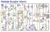
Hello. This post is in regard to the burglar alarm thread posted in the projects area. We are a group of 2 high school students and wish to build this project, although our electronics skills are lacking. We have a few questions regarding the first schematic that was posted, and have circled them in red in the picture below.
1. For the switches we need to know where to purchase them. Can anyone recommend a website?
2. For the rest could we possibly get a quick explanation, and a source to buy from?
Thank you very much
 

Attachments

  • ba1help.jpg
    ba1help.jpg
    65.2 KB · Views: 1,465
SCR - Silicon controlled rectifier.
 
If this is going to be for a house there are two different types of switches, surface mount and recessed.. The surface mount is as its name implies, mounted on the surface of the door/window with wiring exposed. Recessed has the magnet placed in a 3/8" hole drilled into the edge of the door,and the switch in another hole drilled into the door casing, wiring concealed in the wall. Either of these switches should be mounted on the knob side of the door, so that pounding or flexing of the door will set off alarm.
When installing switches the magnet must be placed as close as possible to switch, and in the case of recessed , the alingment must be even...When you get the switches, connect a ohm meter to it and place the magnet near to it to see how much of a gap will open the switch..
 
Hi,

The 'N/C EXIT ENTRY' and 'N/C INSTANT' and 'PA/TAMPER' in the above
drawing are in my opinion meant to indicate a length of thin wire.
The intention being that if the very thin wire is broken, this will
cause the circuit to respond. Such wire may be hidden under door
panelling by the door-lock, so that if the door panels were damaged
to access the lock, the thin wires would be broken. Or maybe around
windows, that sort of thing.

You have circled the 'RESET SW2' along with a set of relay contacts.
The reset is separate from the relay. You may already know this.

Regards, John :)
 
The 'exit/entry ' refers to the door(s) that you would normally use when entering/leaving when alarm is armed. The other doors would be 'instant'.
The delay allows putting the arming station inside the protected area where it will not be prone to attack by burgulars.

You would close all protected door/windows, arm the system, leave thru the delayed 'exit' door before the exit time expires. Entering would be thru the same door, shutting off alarm before enter time expires.
The reason for instant loops is that it gives burgulars less time to find/disable alarm.

The tamper (switch) loop is mostly used on the alarm panel or junction boxes to keep someone (visitor/deliveryman) from disabling the sytem when it's not armed. Can also be used on siren enclosure and wiring to cause alarm to go off instantly if 'tampered' with. Tamper loops are normally '24 hour' meaning they are always active, even when alarm is not armed.
Your drawing only shows one switch/loop for delay/instant but you can have as many as you want. All n/c must be in series and all n/o must be in parallel..
 
Thanks for your help guys/gals. However we are having a few problems locating parts. We cannot find the "SCR 50v 1amp" on any site. Could someone please help us locate it?
Also could someone tell us if these are going to work:

560r:
**broken link removed**

Relay:
**broken link removed**

Thanks a lot.
 
Thanks for answering our questions, but we have something more to ask.
Is the reset switch a spst? Or something else?

Thanks again for your help
 
Status
Not open for further replies.

Latest threads

New Articles From Microcontroller Tips

Back
Top