Continue to Site

Welcome to our site!

Electro Tech is an online community (with over 170,000 members) who enjoy talking about and building electronic circuits, projects and gadgets. To participate you need to register. Registration is free. Click here to register now.

  • Welcome to our site! Electro Tech is an online community (with over 170,000 members) who enjoy talking about and building electronic circuits, projects and gadgets. To participate you need to register. Registration is free. Click here to register now.

Building opamp circuit first time, using LTspice first time.

Status
Not open for further replies.

antknee

New Member
I'm looking to build a circuit using a TCA0372 opamp that will drive a piezo. I discovered LTspice earlier today and it looks excellent. So I have put the circuit into the program. I haven't put in the component values so I can't 'run' it, yet. I'm looking for some input on whether this circuit is going to work as intended. I'm a beginner at electronics so there will probably be a few mistakes.

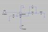
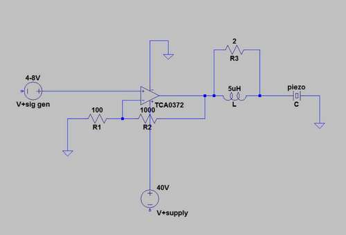
The opamp I'm using is the TCA0372. I've attached the datasheet. It'll be configured for single supply and non inverting. The Gain bandwidth product is just enough.
The input will be from a signal generator 4V-8V , 50ohms, at 100KHz
The supply voltage 40V DC.
Output gain times 10 (20dB)
It'll be driving a piezo 2nF and impedance 100ohms, resonant frequency 100KHz.

arwesd-jpg.40184


The opamp doesn't really come with any application hints,

1) Do I have to protect the power sources with some kind of bypass?

2) Opamps aren't good at driving piezo's so I think standard practise is to use a resistor in parallel to an inductor to compensate. I'm not sure if the values are right though?

3) This opamp doesn't require a pcb layout does it? I need to build it on a breadboard if possible.

Thanks for your input,

Antknee.
 

Attachments

  • tca0372..pdf
    142.1 KB · Views: 390
  • arwesd..jpg
    arwesd..jpg
    8.1 KB · Views: 3,733
Your opamp does not have its input DC biased so it will not do anything.
The feedback resistor to ground needs a series capacitor to stop the opamp from amplifying its input DC bias voltage.
Don't use a supply voltage that is the absolute maximum voltage allowed.
The opamp you selected has a low slew rate that limits its full output to about 25kHz.
 
I have updated the schematic based upon the comments, thanks.

**broken link removed**

It won't run in LTspice, that isn't really a surprise! There are any number of things which could be wrong. In particular I'm not sure how much detail LTspice needs for the input source. I put in a sine wave, AC 6V and the frequency but there were some other input boxes which I didn't understand, so left empty. I also wonder what the arrow is that you get when hovering over a component, I set them all to follow the positive terminal anyhow.

The opamp you selected has a low slew rate that limits its full output to about 25kHz.

That is a little annoying. I was aware of the function of slew rate but its one of the things that I never considered as a possible problem. I might try to put a square wave out of the signal generator.

Thanks.

rtre..jpg
 
Last edited:
Since the input is referenced to GND (i.e. the input signal swings both positive and negative with respect to GND), then you either must power the op-amp on split +/- power supplies, or some how bias the input signal halfway between GND and +27V!

You can temporarily fix your "lack of bias or split-supplies" problem by using "SINE(14 6 10K)", which will cause the +-6V sine wave to ride on top of a 14V positive offset. That will make it simulate, but you still will have to devise a suitable bias network to be used in the real world.

The "AC 6" attached to the input source is only used for .AC simulations; it has no effect whatsoever on a .TRAN simulation.

The "SINE(0 6 10K)" attached to the input source is used only for the .TRAN simulation. Since you are asking LTSpice to simulate for 5 seconds (".TRAN 5"), and since the input source is 10kHz, you are asking for LTSpice to run for 500000 cycles of the input. You do not have enough time to wait for the solution, nor enough disk space for the output file. A more reasonable request would be to simulate at most a few hundred cycles, so change it to ".TRAN 10m", i.e. simulate for 10ms or 100 cycles.
 
Last edited:
I know that is right because it sounds so right! Now I'm sat here chuckling because I have no idea why it is right! :D

I think it might be better to use a dual supply. I decided to use a single supply for this circuit because I thought it would simplify matters. There's nothing simple in electronics is there.

Thanks.
 
Reread my previous post again. I added some more info...

Oh, and in the real world, the polarity of C1 is backwards. LTSpice doesn't care, but the real world will.
 
Last edited:
Hi MikeML, thanks. I understand the concept of biasing so it makes sense. I will update the program.

I could see the program running through lots of cycles, too many! But when I went looking for the right check box I couldn't find it. I will find the command line input and use that instead. It is a useful shortcut.

Regards.
 
You won't be able to drive a piezo with any decent amount of power using an op-amp.

Anyway, here's how to set up a non-inverting amplifier with a gain of 11.
 

Attachments

  • non-invert op-am&#11.PNG
    non-invert op-am&#11.PNG
    13.7 KB · Views: 632
  • non-invert op-am&#11.asc
    1.8 KB · Views: 298
Using a square-wave as the input will not help the poor high frequency slew rate limiting of the opamp.
The output of the opamp cannot change its output amplitude as fast as the transistions in the high frequency so the output will consist of ramps with reduced amplitude than you want.
 
I have got a signal on the piezo. So I think the circuit is ok.

piezo-jpg.40207


It doesn't look like I'll be able to use the TCA0372. I did buy half a dozen different opamps and narrowed the choice down to 2 afterwards. The last option without buying again is the OPA452. I haven't checked whether it has a good enough slew rate and I'm hoping 50mA will be enough current to power the piezo.

I have an analog circuit adapted from a humidifier which will output 30Watts into the piezo and power it without any trouble. I'd just prefer to be able to 'tune' a piezo with a signal generator and amplifier.

I had a look at the attached amplifier.asc but in my copy of LTspice the opamp has been replaced with 'Universalopamp2'. I added the new opamp but it has caused a number of errors, I'm not sure why it isn't working.

Thanks,

Antknee.
 

Attachments

  • piezo..jpg
    piezo..jpg
    44.3 KB · Views: 2,469
  • OPA452..pdf
    382.4 KB · Views: 414
That looks like a horrible waveform, full of crossover distortion.

If all you want to do is connect a transducer to a squarewave source then why no use a half-bridge?

An op-amp isn't the right tool for the job.
 
It isn't the most healthy waveform I've ever seen! lol. It's a little short of a space invader though :D I don't know exactly what cross over distortion is. I will have to play with circuit and see what effect it has.

The piezo needs an inductance shunted with it for good power transfer I think. That is the principle of the humidifier circuit I have, it has never been clear to me whether I'd also have to shunt inductance when used with an amp...? So I don't think a half bridge would work.

I'm replicating a system in my previous job. They used a signal generator into an amplifier into a piezo. So this is the right path to follow. I wish I knew which amp they had used and had their schematic.

Cheers,

Antknee.
 
I'm replicating a system in my previous job. They used a signal generator into an amplifier into a piezo. So this is the right path to follow. I wish I knew which amp they had used and had their schematic.

Then either there was a better way to make your other project or this project is different so needs an alternative approach.

Your piezo just needs a squarewave and there's no point in using an op-amp for that. There are better, more efficient ways of doing it.
 
It might help to say in large part the power consumption of a piezo is determined by the type of pzt used. I'm building the piezo myself, and have ordered the pzt. It is a soft pzt rather than the hard pzt typically used in piezos. The advantages are that the displacement per volt is 2-3 times the harder pzt with lower current requirements if designed properly. The disadvantage is that the quality factor of the piezo is much reduced. So essentially my piezo will very probably work off an operational amplifier. However it will have a comparitively narrow bandwidth and it just won't work at all outside that bandwidth. For example there would be no audible buzz commonly found in piezos, the frequency envelope may be just 1KHz.

An opamp should work with my piezo but its going to have a narrow frequency range and it will be easier to tune the frequency with a signal generator than chase it with analog components. I'm also going to be doing a fair amount of adjusting the piezo myself, so I think this is the best route, there may be others though, I don't have enough experience of electronics to know.

Thanks for the input.
 
It isn't the most healthy waveform I've ever seen! lol. It's a little short of a space invader though :D I don't know exactly what cross over distortion is. I will have to play with circuit and see what effect it has.

The piezo needs an inductance shunted with it for good power transfer I think. That is the principle of the humidifier circuit I have, it has never been clear to me whether I'd also have to shunt inductance when used with an amp...? So I don't think a half bridge would work.

I'm replicating a system in my previous job. They used a signal generator into an amplifier into a piezo. So this is the right path to follow. I wish I knew which amp they had used and had their schematic.

Cheers,

Antknee.

Just wondering here so forgive me if this is way off base, but are you completely sure that they used an op-amp for this and not a power amp? Some power amp ICs (i.e. the LM386) look just like op-amp ICs if you don't know the difference.


Good luck with your project,

Torben
 
Start from the beginning.

What exactly are you trying to do?

You do know that if you want to amplitude modulate the signal, the transducer will need to be able to carry double the bandwidth of the signal you're modulating, unless it's SSB.

For example, if you want to transmit a 15kHz audio signal using a 100kHz, the piezo transducer will need to be able to work from 85kHz to 115kHz. Unfortunately, most piezo traducers can't do that.
 
Hi Torben,

I have looked at power audio amps and they have too much power and complexity, the pcb layout in particular is difficult for me. I'm really looking in the 1-5 Watt range so some opamps can manage this. Finding the right amp is difficult. I have heard of the LM386 and did check its datasheet, I think I overlooked it because it didn't have enough bandwidth gain product.

I have an OPA452 that I'm hopeful will be the right chip (datasheet attached above). I will check the datasheet and hopefully it won't fail on slew rate or some other factor I hadn't thought of. If it does then I will take a look at more power amp ICs.

Thanks for the input and message of good luck,

Antknee.
 
Last edited:
You still haven't told us what you're doing.

I didn't even mention audio amplifiers ICs.
 
Start from the beginning.

What exactly are you trying to do?

You do know that if you want to amplitude modulate the signal, the transducer will need to be able to carry double the bandwidth of the signal you're modulating, unless it's SSB.

For example, if you want to transmit a 15kHz audio signal using a 100kHz, the piezo transducer will need to be able to work from 85kHz to 115kHz. Unfortunately, most piezo traducers can't do that.

I want to send a pure sine wave out of a signal generator. At a single frequency between 50-250KHz. Then have the voltage amplified by 20dB at that single frequency. The piezo will be damped by me so its frequency will change. For example it may start at 230KHz and then be damped to 190KHz, then 120KHz.

I'm making an adjustable frequency device for powering piezo's.
 
Last edited:
Sorry, I missed Torben's post which mentioned audio amplifier ICs.

You said you wanted 30W.

You do know that no op-amp is going to be able to give you that much power?

Most piezos have a pretty high impedance so you'll need quite a high voltage to give you that much power.

As much as I know you don't like it, I think an audio amplifier IC is the best option.
 
Status
Not open for further replies.

Latest threads

New Articles From Microcontroller Tips

Back
Top