Continue to Site

Welcome to our site!

Electro Tech is an online community (with over 170,000 members) who enjoy talking about and building electronic circuits, projects and gadgets. To participate you need to register. Registration is free. Click here to register now.

  • Welcome to our site! Electro Tech is an online community (with over 170,000 members) who enjoy talking about and building electronic circuits, projects and gadgets. To participate you need to register. Registration is free. Click here to register now.

Building an Amplifier

Status
Not open for further replies.

Overclocked

Member
Ive never built a amplifier before, but I will be using the LM1875 20W Chip (also known as a gainclone). Are there any special capacitor or resistor types I need to use for audio applications (ie metal film, carbon, poly, etc) ? This is a very well known circuit in the Audiophile crowd, but erm, they are a very different breed.

I will be doing it by the book, so to speak, using TI's suggested schematic. Why people have reduced the parts count is beyond me. R1 will most likely be substituted for a Log Pot.
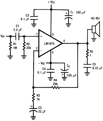
custom_diagram_1_LM1875.gif
 
This LM1875 20W amplifier IC does not produce as much power as a 56W LM3875 or 68W LM3886 gainclone amplifier IC.
Notice that it has a dual polarity power supply that is positive 25VDC and negative 25VDC. The datasheet shows a slightly different circuit that uses only a single positive 50V power supply.
Use a 10k to 20k ohms volume control.

C1 and C5 should be metalized plastic film capacitors and C3 and C4 should be ceramic. C2, C6 and C7 can be electrolytic capacitors.
Use metal film resistors, R5 should be rated for 2W.
 
The feedback resistor R4 should be as close to the chip as possible.
 
This LM1875 20W amplifier IC does not produce as much power as a 56W LM3875 or 68W LM3886 gainclone amplifier IC.
Notice that it has a dual polarity power supply that is positive 25VDC and negative 25VDC. The datasheet shows a slightly different circuit that uses only a single positive 50V power supply.
Use a 10k to 20k ohms volume control.

C1 and C5 should be metalized plastic film capacitors and C3 and C4 should be ceramic. C2, C6 and C7 can be electrolytic capacitors.
Use metal film resistors, R5 should be rated for 2W.

Yeap, you are correct. I dont need 56W of power, but it would make life slightly easier (The speakers I plan on getting can handle it, but 56W is a bit much for computer speakers!). My Power source will consist of two 24vct transformers. One transformer will be for V+ and V-. I'll be regulating it down to 24VDC. I havent decided if I will use a switching regulator or Linear. Logic tells me to use Switching, because of efficiency.

Do said parts for the amp need to be "audio grade" parts or this marketing hype?

This is a big help to me!
 
My Power source will consist of two 24vct transformers. One transformer will be for V+ and V-. I'll be regulating it down to 24VDC. I havent decided if I will use a switching regulator or Linear. Logic tells me to use Switching, because of efficiency.

You do not need to regulate the power supply. Another nice thing about the gainclone.
The LM1875 will take up to 60 volts.
 
You do not need to regulate the power supply. Another nice thing about the gainclone.
The LM1875 will take up to 60 volts.
That is true, but a 24V Transformer gives roughly 33vDC. Still need to drop a few volts to be safe. I will be using 4x4,700uF Caps per rail though (which is quite expensive!). The alternative would be to just upgrade to the LM3875, but that doesnt justify the jump in price.
 
I agree that the amplifier will not need regulators.
You also do not need two center-tapped transformers. A single 36V center-tapped transformer, two rectifier diodes and two 4700uF capacitors will be the power supply.
 
I agree that the amplifier will not need regulators.
You also do not need two center-tapped transformers. A single 36V center-tapped transformer, two rectifier diodes and two 4700uF capacitors will be the power supply.
I was trying to avoid buying one, because this is what I have on hand, and I cant seem to locate a decent transformer that doesnt cost me a fortune. Ive been searching surplus sites and ebay the past few days with no luck.

EDIT: I stand corrected. Mouser is great for small stuff, but it looks like digikey is the winner for transformers

https://www.digikey.com/product-detail/en/VPT36-2780/237-1341-ND/2090079

Seems reasonable. Im worried about the 100VA limit though
 
Last edited:
The 100VA transformer will be fine for your 20W amplifier. When producing 20W into an 8 ohm speaker the amplifier will heat with about 18W so the transformer will be supplying 38VA and will not get hot but just fairly warm.
In the future if you try a 4 ohm speaker then the amplifier will heat with about 33W and the transformer will be supplying 53VA which is also fine.
You could even use this transformer to supply two of these amplifiers driving 8 ohm speakers.

Thats what I plan to do. Two monoblocks for stereo, each speaker is 4 to 8 Ohms. I will be using these speakers. My second choice is probably these, but I read that something changed inside.

Can you explain how you arrived at the 38VA per Channel?
 
Last edited:
A review of the little Micca speakers said they were pretty good for their size. A review of maybe the Dayton speakers you linked to said they sounded horrible and were returned.

The datasheet for the LM1875 amplifier shows on a graph 18W of dissipation (heating) when its output is 20W into 8 ohms. You need a heatsink large enough to remove 18W of heat, but it will not be at full blast continuously (unless you play acid rock) so you can cheat a little on the heatsink size.
 
Would using schottky 3A rectifiers vs regular PN silicon for a full wave bridge represent a worthwhile efficiency gain?

BTW, are there synchronous bridge rectifier modules sold as a single part for this level of power supply?
 
Last edited:
Would using schottky 3A rectifiers vs regular PN silicon for a full wave bridge represent a worthwhile efficiency gain?

No, it's a bad idea to use Schottky, and there's no need or advantage unless you're running at higher frequencies (such as switch-mode supplies). Schottky have much higher reverse leakage, and their higher switching speed means they generate more interference and noise.

BTW, are there synchronous bridge rectifier modules sold as a single part for this level of power supply?

I've no idea what you mean by that?, what's 'synchronous' about it? - you just need a standard bridge rectifier, or four rectifiers and make your own.
 
A review of the little Micca speakers said they were pretty good for their size. A review of maybe the Dayton speakers you linked to said they sounded horrible and were returned.

The datasheet for the LM1875 amplifier shows on a graph 18W of dissipation (heating) when its output is 20W into 8 ohms. You need a heatsink large enough to remove 18W of heat, but it will not be at full blast continuously (unless you play acid rock) so you can cheat a little on the heatsink size.

My Plans are to construct a case out of Aluminum or plastic, however, I want to be fancy and make a nice copper heatsink from 1'' stock on my lathe. I have to remember to use Mica insulators though. It wont be continuously high, I almost never play my games on full blast. The Speakers I have now sound distorted when they get loud. Most of the time its on half volume anyway.

ADD: Are Extra Tolerance Parts worth it? ie 0.1%? I usually use 1% and find they dont vary much.
 
Last edited:
A heatsink must have a high surface area to feed the heat into ambient air. Heatsinks use many fins to produce a high surface area in a small size. If they are black then they radiate some heat away.
Can your lathe make many fins?

Sound distorts when the amplifier clips because the attempted volume is louder than its maximum output. Simply turn down the volume until the amplifier does not clip anymore or use an amplifier with a much higher output power and/or a speaker that is more efficient.
I have never heard an overloaded speaker distort because I never overload anything. I have never heard my home sound system or my car sound system distort because they are NEVER overloaded. Even my modified clock radio never distorts.

I have designed and built thousands of circuits. I always used 5% resistors and capacitors. Everything worked and still works perfectly.
 
No, it's a bad idea to use Schottky, and there's no need or advantage unless you're running at higher frequencies (such as switch-mode supplies). Schottky have much higher reverse leakage, and their higher switching speed means they generate more interference and noise.


I've no idea what you mean by that?, what's 'synchronous' about it? - you just need a standard bridge rectifier, or four rectifiers and make your own.

A synchronous rectifier using MOSFETs as very low loss diodes. It seems that I found a synchronous controller here:
http://cds.linear.com/docs/en/datasheet/4320fb.pdf
I am not sure I agree with Schottky diodes being noiser....
http://www.edaboard.com/thread254176.html
**broken link removed**

Also a Schottky inherently drops less Vf and improves rectification efficiency. The reverse leakage doesn't seem to matter in this application, in fact, it can serve to discharge any smoothing capacitors after power down preventing potential surprises from a high current short long after power down.

I found this made interesting reading:
http://www.hagtech.com/pdf/snubber.pdf
 
Last edited:
A heatsink must have a high surface area to feed the heat into ambient air. Heatsinks use many fins to produce a high surface area in a small size. If they are black then they radiate some heat away.
Can your lathe make many fins?

Yes in fact. Ive made a nice LED heatsink for a 3.6v x 400mA LED, and it cools it quite well (even though its not much). My Inspiration comes from here, but it will be made of copper instead. Of course, I'll test it with a 30W Load before hand, even though I do have a TON of heatsinks lying around.

Would you recommend using fuses? I trust that the chips thermal regulation and shutdown should handle any type of short.
 
Also a Schottky inherently drops less Vf and improves rectification efficiency. The reverse leakage doesn't seem to matter in this application.

The reverse leakage reduces efficiency, by wasting energy leaking back through the rectifiers - like I said, no point for 50/60Hz rectification.
 
As For Star Grounding, How do I go about doing it? Im thinking its something like this:

Chassis: Earth Ground and center tap from the transformer
Input Grounds all go on one lug and that lug is on the chassis
Power Grounds all go on one lug and that lug is on the chassis
Output Grounds all go on one lug and that lug is on the chassis

Or do all the grounds get one lug on the chassis?
 
Status
Not open for further replies.

Latest threads

New Articles From Microcontroller Tips

Back
Top