Continue to Site

Welcome to our site!

Electro Tech is an online community (with over 170,000 members) who enjoy talking about and building electronic circuits, projects and gadgets. To participate you need to register. Registration is free. Click here to register now.

  • Welcome to our site! Electro Tech is an online community (with over 170,000 members) who enjoy talking about and building electronic circuits, projects and gadgets. To participate you need to register. Registration is free. Click here to register now.

building a signal modifier?

Status
Not open for further replies.

99 R/T

New Member
I have a controller that can scale a single DCV input/output, but I need need to build a box that can scale 3 additional DCV inputs/outputs with independent signals, all the same amount in relation to the output of the single controller channel.

The voltages are not constant, they swing from .1 to 1V rather randomly.
IE:

input--------- controller scale--------- output
#1=.4vDC -----------(+.2v)-----------#1=.6vDC
#2=.9vDC -----------------------------#2=1.0vDC
#3=.45vDC ----------------------------#3=.65vDC
#4=.5vDC -----------------------------#4=.7vDC

input--------- controller scale--------- output
#1=.7vDC ----------(-.2mv)--------#1=.5vDC
#2=.9vDC ---------------------------#2=.7vDC
#3=.2vDC --------------------------#3=.1vDC
#4=.4vDC ---------------------------#4=.4vDC

Input/Output signal will range from .1vDC-1.0vDC, with a voltage clamp @ .1v and 1.0v.

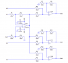
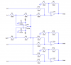
-Can I use the Vout of a differential amplifier between In#1 and Out#1 as the V1in on a summing amplifier for Inputs#2-#4 and then invert the outputs?

IE:

Differential Amplifier-

V1=.4V
V2=.6V
Vout=.2V

Summing Amplifier#1-

V1=.2
V2=.9
Vout=-1.2, invert to +1.2 (step2, how to clamp@1V?)

Summing Amplifier#2-

V1=.2
V2=.45
Vout=-.65, invert to+.65

Summing Amplifier#3-

V1=.2
V2=.5
Vout=-.7, invert to +.7

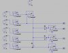
I'm just learning about OP Amps, I threw together a basic schematic, thought I'm lost as how to figure the correct resistances. I'm looking for a gain of "0", are resistors necessary?

Is there a simpler way to accomplish this?

Thanks in advance,

John
 

Attachments

  • opamp2.jpg
    opamp2.jpg
    67 KB · Views: 235
I don't understand what you need, and I suspect no one else does.
This section makes no sense:

input--------- controller scale--------- output
#1=.4vDC -----------(+.2v)-----------#1=.6vDC
#2=.9vDC -----------------------------#2=1.0vDC
#3=.45vDC ----------------------------#3=.65vDC
#4=.5vDC -----------------------------#4=.7vDC

input--------- controller scale--------- output
#1=.7vDC ----------(-.2mv)--------#1=.5vDC
#2=.9vDC ---------------------------#2=.7vDC
#3=.2vDC --------------------------#3=.1vDC
#4=.4vDC ---------------------------#4=.4vDC
For example, you show input #2 with 0.9V input, and two different output values.
I didn't read the rest of your post, because I assumed it was related to the above.
 
I don't understand what you need, and I suspect no one else does.
This section makes no sense:

For example, you show input #2 with 0.9V input, and two different output values.
I didn't read the rest of your post, because I assumed it was related to the above.

Read the rest of the post and maybe it will make sense to you.

Ok, I'll break it down for you.

You've got an Oxygen sensor (Input #1) , it creates a voltage through a chemical reaction, this voltage varies between .1V and 1.0V depending on the oxygen content of a gas stream (stream #1).

I've got a "piggyback" that modifies the voltage from this sensor depending on several variables. (Controller scale), and outputs it (Output #1)

This is all fine and dandy, everything works great.

Now, here's the problem:

I also have 3 more oxygen sensors (Input #2, Input #3, Input #4) that are each in their own separate gas stream.

Hence the voltages from all inputs are almost never the same. 4 sensors, 4 locations, 4 different voltages. But they all follow the same "range" of .1V to 1.0V

I need to build a circuit that can take Input #1 and subtract it from Output #1 (using a differential OP Amp?) to get the voltage "difference" .

Follow me?

Now I need to take this "difference" and add it to each of the other sensor values.

Make sense now?

If Input1= .2V and Output1=.2V then the difference is 0, all signals stay the same.

If Input1=.2V and Output1=.5V then the difference is .3V, all signals need to have .3V added to them.

If Input1 = .2V and Output1=.1V then the difference is -.1V, all signals need to have -.1V added to them (in effect they all need to drop in voltage by .1V).

Easier to understand?

John
 
Is the relationship between Input1 and Output1 predetermined?

Or are both Input1, and Output1, inputs to the proposed circuit?
 
Is the relationship between Input1 and Output1 predetermined?

Or are both Input1, and Output1, inputs to the proposed circuit?

Input1, Input2, Input3, Input4, and Output1 are predetermined, I only list I#1 and O#1 because it is necessary to know the difference between I#1 and O#1 in order to "process" the other signals.
 
EDIT: Disregard the schematic in post #1, as the input numbers don't correspond with the text of my post.
 
That makes more sense. The circuit below should work for you.
 

Attachments

  • signal modifier.PNG
    signal modifier.PNG
    18.7 KB · Views: 300
Thanks :) I'll give it a shot next weekend...

Once concern though, won't there be issues of "crosstalk" between the lines?
 
Thanks :) I'll give it a shot next weekend...

Once concern though, won't there be issues of "crosstalk" between the lines?
Not unless the output impedance of your sources (inputs) is very high. I made all the resistors 100k to hopefully avoid that potential problem.
 
Not unless the output impedance of your sources (inputs) is very high. I made all the resistors 100k to hopefully avoid that potential problem.

The output impedance of the sensors is ~22Mohm. Should I build voltage followers/buffers into the inputs?
 
The output impedance of the sensors is ~22Mohm. Should I build voltage followers/buffers into the inputs?
Do you have a datasheet that we can look at? I am concerned about their ability to provide a current path for the op amp inputs, even with voltage followers.
 
Do you have a datasheet that we can look at? I am concerned about their ability to provide a current path for the op amp inputs, even with voltage followers.

Ugh, that's going to take a while. I'll see what I can dig up.

Thanks for all the help so far, I'll keep you posted.

John
 
Not much info out there, I couldn't find any info on the actual sensors I'm using (other than make/model interchange), it looks like most of the sensors are generic with only the plug being different for each application. The only big difference is between EGO/HEGO being a 0-1V signal and UEGO being a 0-5V signal. I'm running HEGOs.


Split Second (distributor of a relabeled OEM HEGO sensor):
https://www.electro-tech-online.com/custompdfs/2008/07/ego1ds.pdf

Bosch LSU UEGO:
https://www.electro-tech-online.com/custompdfs/2008/07/LSU42.pdf

National Semiconductor Lambda interface amplifier:
**broken link removed**
 
Where did you get the 22Meg number?

From a webarchive from a mailing list (that I just realized is about a decade and a half old...)

**broken link removed**

EDIT: the resistance is only >1Mohm until the sensor heats up, then is runs ~10Kohm.
 
Last edited:
You should buffer all your sensors with voltage followers. If Output1 impedance is not low (<1k or so) compared to 100k, you should buffer it too.
I don't know how to edit an attachment after the 60 min grace period has expired. I made an error on the previous schematic. Here is the corrected one (still without input buffers).
 

Attachments

  • signal modifier.PNG
    signal modifier.PNG
    18.9 KB · Views: 180
You should buffer all your sensors with voltage followers. If Output1 impedance is not low (<1k or so) compared to 100k, you should buffer it too.
I don't know how to edit an attachment after the 60 min grace period has expired. I made an error on the previous schematic. Here is the corrected one (still without input buffers).

I'll give it a shot, thanks :)
 
Status
Not open for further replies.

Latest threads

Back
Top