Hey guys, im working at a schoolproject with a friend of mine where we are bulding an entire alarmsystem with several alarms and a central station which handles these alarms.
I am trying to construct a proper working motion sensor circuit and have found an idea with the use of IR diodes. Also I would like to include some ambient light filtration.
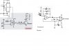
In the included file there is a sender circuit, which includes a timer circuit which sends impulses into a comparator. I have a diode connected in the right side which sends pulses of light out. This diode is connected to a voltage source so I can send some strong and powerful pulses without burning the diode out.
In the receiver part I have a narrowband amplifier and the circuit as a whole should filtrate the light away. I would like to say I have not made these myself but found the receiver and sender from different circuits and would like to put them together. I would like to hear your opinion about this setup and if it will work or you have some ideas which may make the circuit as a whole more easy.
Any help is appreciated, thansk
I am trying to construct a proper working motion sensor circuit and have found an idea with the use of IR diodes. Also I would like to include some ambient light filtration.
In the included file there is a sender circuit, which includes a timer circuit which sends impulses into a comparator. I have a diode connected in the right side which sends pulses of light out. This diode is connected to a voltage source so I can send some strong and powerful pulses without burning the diode out.
In the receiver part I have a narrowband amplifier and the circuit as a whole should filtrate the light away. I would like to say I have not made these myself but found the receiver and sender from different circuits and would like to put them together. I would like to hear your opinion about this setup and if it will work or you have some ideas which may make the circuit as a whole more easy.
Any help is appreciated, thansk
Attachments
Last edited:
