Hi,
We have to do a supercap charger. It just has to keep a 25F supercap charged up to 6V. We choose 20A charge current. The supercap will be getting discharged every 15 seconds or so.
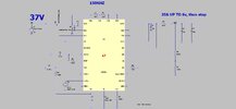
Vin = 37V
The attached LT8391 sim in LTspice does the job….its set for 150khz, but when the supercap is near zero volts, the LT8391 sim conveniently reduces the switching frequency so the on_time is more realistic. We wonder if the actual real LT8391 chip will do this?..because the datasheet doesn’t say it will.
Also, the LT8391 is a 4 switch buckboost controller…however, since we only ever wish to use it in Buck mode, we will only fit the two sync Buck FETs…do you think this is OK?…it certainly works in the sim…datasheet doesn’t say though.
Also, concerning the LSP_LSN current sense resistor, it is in the (noisy) switching node of the Buck…..but since we are not using buckboost mode, is it now ok for us to move the LSP_LSN sense resistor to just downstream of the buck inductor, so that it is now no longer in the noisy switching node?...once again, this certainly works in the LTspice sim, but will it work in the real hardware?
LT8391
Attachments
We have to do a supercap charger. It just has to keep a 25F supercap charged up to 6V. We choose 20A charge current. The supercap will be getting discharged every 15 seconds or so.
Vin = 37V
The attached LT8391 sim in LTspice does the job….its set for 150khz, but when the supercap is near zero volts, the LT8391 sim conveniently reduces the switching frequency so the on_time is more realistic. We wonder if the actual real LT8391 chip will do this?..because the datasheet doesn’t say it will.
Also, the LT8391 is a 4 switch buckboost controller…however, since we only ever wish to use it in Buck mode, we will only fit the two sync Buck FETs…do you think this is OK?…it certainly works in the sim…datasheet doesn’t say though.
Also, concerning the LSP_LSN current sense resistor, it is in the (noisy) switching node of the Buck…..but since we are not using buckboost mode, is it now ok for us to move the LSP_LSN sense resistor to just downstream of the buck inductor, so that it is now no longer in the noisy switching node?...once again, this certainly works in the LTspice sim, but will it work in the real hardware?
LT8391
Attachments