Electro Tech is an online community (with over 170,000 members) who enjoy talking about and building electronic circuits, projects and gadgets. To participate you need to register. Registration is free. Click here to register now.
Welcome to our site! Electro Tech is an online community (with over 170,000 members) who enjoy talking about and building electronic circuits, projects and gadgets. To participate you need to register. Registration is free. Click here to register now.
i am trying to build a smps ( buck converter) but i am getting nowhere fast! i need to take a standard uk outlet voltage (240V ac) and convert it into 94V dc at around 16A. any ideas on a rough design?
Judging from your location; You may need to add power factor correction to your battery charger.
If this is your first smps you should pick a smaller project.
Do you need isolation? A simple buck converter leaves the batteries on the power line.
Method 1:
High frequency filter.
Full wave diode bridge.
Large filter capacitors.
Switcher
Transformer (isolation) Inductor for no isolation
Diodes
Capacitors
Battery
Method 2:
High frequency filter.
Full wave diode bridge.
Power factor switcher
Inductor
Diode
Large filter capacitors.
Switcher
Transformer
Diodes
Capacitors
Battery
Method 3:
High frequency filter.
Full wave diode bridge.
Power factor switcher or sm switcher
Transformer or (inductor)
Diodes
Capacitors
Battery
In method 3 there is no large filter capacitors. I often charge batteries with out filtering the 60/50hz power line. The charging current is 120 hertz half sign wave. I found that charging batteries with 120hz pulses is good. My truck charges its battery with pulses not DC.
What is Power Factor correction.
Many power supplies only pull power from the line at the very peak of the 60 cycle voltage. If you need an average of 7 amps from the line, the peaks may be 40 amps. With power factor correction the current and voltage look much like a resistive load. The current is sign wave. Many countries require large power supplies to not distort the power line.
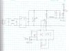
Capacitor C4 is optional. The UC3842 turns on the FET. Current from the power line flows through the battery, through the inductor, FET, resistor and around. When the current builds up to 1 volt across the resistor then the 3842 will turn off the FET. In 10uS the FET will turn back on. This is the full current charge mode.
The TL431 decides when the battery is charged. When the battery hits “charged voltage” current goes thought the opto-coupler, pulling up on the error amp input to the 3842. The FET will open at a smaller current. The charger will start in constant current mode and slowly shift to constant voltage mode.
It will be much safer to start out with 1 small 12 V. battery and a 24 volt current limited power supply. Get it running safely. Then move up to higher voltages.
Get an isolation transformer. (220 to 220) Add a fuse. This way you might survive playing with this charger. After it works then remove the transformer.
Danger this design leaves the battery on the power line. You will get shocked by touching the battery terminals. That is OK, I just want everyone to know!
There are some pieces left out. I think you can fix that.
Also, I'd like to see what inductor you recommend, most switching power supplies of this size use a full bridge and some even use quasi-resonant switching to cut the losses even further.
If this is used I suggest a contactor across the mains input that completely disconnects the battery bank from the device that uses it as soon as mains is connected to prevent death by electric shock. Is this for a mobility vehicle by any chance ?
I don’t see that the battery has to be isolated. A 94 volt battery will knock you on your ass if you touch the terminals. If it is connected to the power line it will still knock you on your behind.
This design; FET and Diode see only 300 volts. In many supplies the FET sees 2x the supply. Here the FET sees only 1x the supply. There is no need for a snubber. Normally I would use 600/800 or even 1000 volt FETs which are slow. Here with a 500 volt FET and diode the AC losses will be lower.
If the inductor was designed for discontinuous mode the AC loses will be low. Continuous mode will increase the AC losses and then I might think about resonant.
A single FET single Diode design is pretty simple.
I don’t see that the battery has to be isolated. A 94 volt battery will knock you on your ass if you touch the terminals. If it is connected to the power line it will still knock you on your behind. .
94VDC isn't 100% safe but it's still unlikely that it will severely hurt you, especially if you have dry skin.
230VAC is much more dangerous, as it's AC for a start and the peak voltage is three and a half times higher.
Another advantage of isolation is that you'll have to touch both battery terminals to recieve a shock but you'll recieve a shock from either terminal if it isn't isolated.
I would agree if we're talking about 1kVDC vs 1kVAC.
However, in this case we're talking about 94VDC vs 230VAC, it's pretty obvious that the AC is far worse here.
The IEE regulations even seem to agree that AC is more hazardous than DC, the minimum touch voltage is 25V for AC and 60V for DC. You could build a power supply with a 30V mains transformer but you only have to protect the user from the mains and the 30VAC on the transformer's secondary, not the 41VDC present on the output of the rectifiers, to comply with the IEE regulations.
By the way, AC can also make you freeze, my mum told me a story about a neighbour who nearly got electricuted from by a dodgy electric drill; he couldn't let go of it, the current had frozen his mussels.
I think this supply should run at 100 to 200khz. Most micros cannot do PWM at high speed.
There are analog parts that do the UC3843 and Power Factor logic.
The building codes I work with treat 94VDC the same as 230VAC. Double insulation, all connections in boxes, etc. The high voltage solar cells and batteries have to be wired the same as AC wiring. (any thing above 42 volts???)
This site uses cookies to help personalise content, tailor your experience and to keep you logged in if you register.
By continuing to use this site, you are consenting to our use of cookies.