Continue to Site

Welcome to our site!

Electro Tech is an online community (with over 170,000 members) who enjoy talking about and building electronic circuits, projects and gadgets. To participate you need to register. Registration is free. Click here to register now.

  • Welcome to our site! Electro Tech is an online community (with over 170,000 members) who enjoy talking about and building electronic circuits, projects and gadgets. To participate you need to register. Registration is free. Click here to register now.

Buck Boost Converter Help Please

Status
Not open for further replies.

PHiiZY

New Member
Hey guys,

first post! I am trying to build a buck boost converter for a project. Input should be 5V and output should be -5V but not necessarily. It can be between -4V and -6V. Output load is set to 1k but it should be able to take different load resistors ranging from lets say 100 ohms to 5k ohms and still be able to produce an output of -5V.

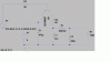
My last attempt was giving me an output of -5V however, it was not built to support different load resistors. My circuit is illustrated in "Pic_old". (See Attachments)

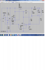
So I modified it according to what I have read from textbooks and I built another circuit "Pic_new". (See Attachments)

Problem is when I simulate (Finally got it to simulate. I was having problems with the comparator), it doesnt produce correct results. Now, I understand the values of my my resistors and capacitors and inductor might not be right, but I am not even able to get a negative output like before from "Pic_old".

So if anyone can shed some light on this, I would really appreciate it.

Thanks in advance

PY
 

Attachments

  • Pic_old.gif
    Pic_old.gif
    346.6 KB · Views: 251
  • Pic_new.gif
    Pic_new.gif
    229.5 KB · Views: 226
The comparator has a pos. voltage on one input and a neg voltage on the other input. The 2 inputs will never activate the compare logic.
 
hi PH,

You have no power supplies to the comparator pins...!:rolleyes:

E
 
Without quoting the obvious, your comparator has no supply voltage. LTSpice is fussy about engineering assumptions. I tried the sim and it won't work without serious mods.
 
Firstly, I am still sort of at the bottom of the learning curve so forgive me if I say something stupid.
@crutschow I am only trying to build one using simple components, resistors, caps, inductors and the comparator or op amps.
Ok so I changed a few things around in my circuit based on your posts. My reference voltage for the comparator is now 5V at the inverting terminal and my non-inverting terminal is now the negative voltage (decay from 0V to roughly -19V. And now (although not what I want) output drops down to -35V and then very slowly comes back up to about -18V. I am not too sure why it does this so if anyone knows, that would be great.
So right now, since the non-inverting terminal voltage is less than the inverting terminal voltage, the output will be the most negative voltage it can output and this is limited by the supply voltage. So my first question is how is the output going all the way down to -19V and how do I fix it? Secondly, what components (resistors, caps, etc) should I focus on changing as to increase my output from -35V to -5V and why (so I know for my understanding)?
I have also posted a picture of the circuit so any further advice would be great.
Thanks
PY
 
The comparator has a pos. voltage on one input and a neg voltage on the other input. The 2 inputs will never activate the compare logic.

Hi, I am not too sure what you mean exactly. Isn't the compare logic activating all the time, since the +terminal voltage is less than the -terminal voltage all the time? But then from what I understand, my output voltage from the comparator is always going to be negative. What happens from here?
 
I am supposing that the comparator is in the circuit to regulate the voltage. Comparing the negative voltage to a reference voltage. If I am supposing correctly then the 2 input voltages to the comparator should be equal to each other.

In your drawing.
The - input to the comparator is a positive 2.5 volts set by the zener diode while the + input is a negative 2.5 volts. Different polarities on the inputs instead of being equal.
 
Last edited:
The reason I have a comparator in there is because I was told that it is part of a feedback portion of the circuit, that I will need to make sure my whole circuit outputs constant -5V for different resistor values.

So, what your saying is that I need to match both inputs to the comparator for it to operate correctly? If so, how would I go about doing that? And I think I will need to look back at my theory on comparators once again. haha

Thanks
 
For the comparator to work, the negative voltage to the input of the comparator would need to be shifted up 5 volts in order to be compared to the reference. This could probably be done with a zener diode.

Crutschow posted a circuit at post #5 which is a little power hungry and no regulation. I took his design and adjusted it a little.
A 100 ohm load is about the limit.
neg5.JPG
 

Attachments

  • neg5.asc
    2.9 KB · Views: 161
.............................

Crutschow posted a circuit at post #5 which is a little power hungry and no regulation. I took his design and adjusted it a little.
A 100 ohm load is about the limit.
If you replace the BJT's in my circuit with logic-level complementary MOSFETs, you can increase the current while still maintaining greater than -4V output.
 
For this project, I would not like to use the NE555 because I am only allowed to use inductors, capacitors, resistors, diodes (whichever type), mosfets, bjts, and op amps to build this circuit.
 
The 555 used in the circuit posted is nothing more than an oscillator. It could be replaced with an op-amp or transistor osc.
 
For this project, I would not like to use the NE555 because I am only allowed to use inductors, capacitors, resistors, diodes (whichever type), mosfets, bjts, and op amps to build this circuit.
How about comparators?
 
Hey guys, sorry. I was busy and could not find the time to reply. Anyways, here is the circuit now. I was messing around with the circuit and with some advice from a professor at my university, I have come up with this and it works. It outputs roughly -5V at anything from 700 ohms to infinity load resistance.

Pic_newfinal.jpg

My next new problem is I am not too sure how the feedback portion of the circuit works. So what I am looking for is an explanation. I know how a buck boost converter works without any feedback. The on and off switching and how it affects the inductor and capacitor. I am fairly comfortable with that. I know what a comparator does. I know what a nor gate does. But when everything comes together, I start getting confused.

Also, if anyone has any reference books I could buy or websites or any information I could look at or research, I would highly appreciate it. Anything to gain knowledge.

Few more things:

1) In my circuit, I have an inverter and an or gate because LTspice does not have a nor gate in its database. Just putting it out there.

2) Apparently that reference zener diode and the 1k feedback resistor are not needed. Again, I am not too sure why. That positive terminal is meant to have 5 V reference going through so it makes sense not to include the zener diode and the 1k feedback resistor.

3) Are there any ways to optimize this circuit? I am sure there are, but keeping things simple, such as changing the value of the inductor to another value or changing the diode I am using, etc.

Hopefully, I reach out to a few of you. I am here to learn.

Regards

PY
 
Hello,

Someone already mentioned that the comparator has a positive voltage reference and a negative feedback from the output. That's not going to work. The comparator must have both signals of the same polarity and the same voltage level at the regulation point. That's assuming everything else works too.
 
Boost converter

Take a look at this one.

R8 makes the voltage on the comparator positive instead of below ground like you have it.
U1 is just an oscillator and U5 shuts of the oscillator and the FET when the voltage goes more negative that the reference set by the diode.
 

Attachments

  • Boost.png
    Boost.png
    152.4 KB · Views: 208
Hi there ronv,

That's a decent idea but you can not reference it to the input voltage because usually with regulators the input voltage is subject to wide variation. Instead, reference it to a voltage reference diode or zener. There is already a zener in the circuit too so maybe that one.
 
Status
Not open for further replies.

Latest threads

Back
Top