Continue to Site

Welcome to our site!

Electro Tech is an online community (with over 170,000 members) who enjoy talking about and building electronic circuits, projects and gadgets. To participate you need to register. Registration is free. Click here to register now.

  • Welcome to our site! Electro Tech is an online community (with over 170,000 members) who enjoy talking about and building electronic circuits, projects and gadgets. To participate you need to register. Registration is free. Click here to register now.

Brushed D.C. 12V rotor test

Status
Not open for further replies.

brujet

New Member
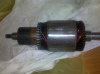
Hello! Can anyone tell me how can I test rotor of Brushed D.C. motor 12V, 5,5 kW, it has 4 brushes,and when I try to measure resistance tween any small plates on colector it allways shows cca 1ohm!? Is there any other way I can test it. And also can I put any kind of paint on stator core(very rusty) or it will have influence on magnetism? Thanks.
 

Attachments

  • rotor.jpg
    rotor.jpg
    349.2 KB · Views: 358
Last edited:
are you sure 5.5 kW because that equals 458.33 amps :eek:

i think there are places that you can take things like motors and they do a full safety test on to make sure they work and are safe to use.
 
Last edited:
The standard test for brushed armateurs is to place them in an AC magnetic field and see if any of their turns are shorted by noticing how much the current changes in the magnetid field generator.

The machine is called a "growler" and it is made with a magnetic core having a gap large enough to lay an armateur in. When the gap is empty, very little current flows in the primary. When you lay a good armateur in the gap, the exciting current increases, and as you rotate the armateur to bring different sections of it into the magnetic field, the growler makes noises. If you place a shorted turn in the magnetic gap, the current goes WAY up.

Anyway...you need a motor/generator re-winding shop to find a growler.
 
Yes I am sure,it has fuse of 400 amps,it is bowthruster for helping boat to turn. Thanks for "growler" but is there anything that I can use things I have at home like multimeter ....
 
The simplest way to test the rotor is to assemble the motor and put 2v on two of the brushes and hold the shaft with a wrench. Gradually turn the shaft and feel the constant torque.
 
The simplest way to test the rotor is to assemble the motor and put 2v on two of the brushes and hold the shaft with a wrench. Gradually turn the shaft and feel the constant torque.

Thanks I try tomorrow ! And what about painting the stator core (the one with lil ribs) it gets really rusty??
 
Tested it.....works fine,had constant torque..THANKS:) I have one more question for you....since my motor doesnt have thermal protection...can I install one in stator windings and how? I read something about thermistor PTC? So what do I need more to have my motor switched off by overheating?
 
You can sneak a temperature sensor into the stator fairly easily. There are seveal kinds that are really tiny. Then you need to use the measurement, in whatever form the sensor provides, to control some MASSIVE switches. The sensor is the first decision. A thermistor with a differential amplifier? A snap switch? A temperature chip that outputs 10 millivolts per degree? It's about how accurate you want to be and how fast you need it to detect.
 
Well I dunno how accurate I need to be....I know that I need protection for 105 degrees celsius,and how fast.....depends on how long can winding hold that temperature...
 
The datasheet left out the 2 of the most important things...time constant and size, as in "how fast?" and "will it fit?". Keep looking or ask the Otter company directly.

And, while we're at it, if the bow thruster goes into automatic "safety off" at a bad time, how many people might be killed? Perhaps the sensor should only ring a bell to notify you something is wrong.
 
Status
Not open for further replies.

Latest threads

New Articles From Microcontroller Tips

Back
Top