mstechca
New Member
...so maybe my superregen has a colpitts in it.
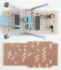
I have it all on a breadboard, and when I calculated the frequency with the correct inductors, it was about 29Mhz than it should be. However, when I added 0.03uH (I assumed this number) to my 0.1uH, just because I think the breadboard adds inductance, I get closer to the correct value. In fact, I was only about 1Mhz away.
So just exactly, what is the inductance between any two connection points, provided they aren't connected to each other internally?
and my inductors have some wire exposed because I have them in a stand-up fashion, so I think there is some inductance there.
I don't make my own inductors. I use store-bought ones.
So what is the inductance per mm of the wire? It is about the same AWG of wire normal 1/4 watt resistors are attached to, and it is the same colour as well, and no windings on the wire.
I don't need approximations, but I need EXACT answers, because I am going to make a radio that changes stations upon the push of a button.
Later, I am going to get myself a whole bunch of 1pF capacitors so that I can build a chain of values and then be able to flip through many stations (well over 100). I already have a counter IC which I will use as well.
why capacitors over wire pieces for inductors? I think that the larger the capacitor in the LC circuit, the better the quality, because it is the inductor that makes a large amount of resistance.