Electro Tech is an online community (with over 170,000 members) who enjoy talking about and building electronic circuits, projects and gadgets. To participate you need to register. Registration is free. Click here to register now.
Welcome to our site! Electro Tech is an online community (with over 170,000 members) who enjoy talking about and building electronic circuits, projects and gadgets. To participate you need to register. Registration is free. Click here to register now.
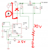
i just made another circuit kind same as this i get 30~32 v Vout if there is no load connected in output,
but when i put a certain load the voltage drops depends on the resistor .Is there a way that i can get a Vout 30~31 v even it has a load in output ?
You have many problems. Some were said in posts above.
Power to IC is wrong. In real life this will kill the IC. In spice it will not work.
No ground connection for input voltage.
No voltage divider on Vout to Vf.
....The IC has one job. To keep Vfb at 2.5V. Because you are sending 15 to 30 volts into Vfb the IC thinks the output voltage is too high so it stops working. In real life this kills the IC. You must divide 30V down to 2.5V. The IC will then egulate to keep 2.5v at Vfb.
Time stamp error: I don't know but look it up under help. There is some "time setting" this is set too small.
This is not how the IC was designed to be used but it is mostly working.
Normally SENSE looks at a resistor in the source of the MOSFET. (with a small RC).
The OSC cap is very large. 1.67uF?? The IC must be working very slow.
The error amp is strange. Move C4 to where R2 is. Remove R2. Make R3 10k or 33k.
HAVE YOU READ THE DATE SHEET FOR THE IC? LOOK AT APPLICATION CIRCUITS.
Diode voltage: The diode will see 30V. Get a 50, 60 or maybe a 100V diode.
Diode Current: Average current is IoutMax. Peak current is about 2xIouts maybe 3xIout.
Because you are not using Isenc pin there is no current limit! The current during start up is very large.
You are using the IC in voltage mode. It should be used in current mode to make it more stable and have current limit.
This site uses cookies to help personalise content, tailor your experience and to keep you logged in if you register.
By continuing to use this site, you are consenting to our use of cookies.