Continue to Site

Welcome to our site!

Electro Tech is an online community (with over 170,000 members) who enjoy talking about and building electronic circuits, projects and gadgets. To participate you need to register. Registration is free. Click here to register now.

  • Welcome to our site! Electro Tech is an online community (with over 170,000 members) who enjoy talking about and building electronic circuits, projects and gadgets. To participate you need to register. Registration is free. Click here to register now.

Bode Plot Wien Bridge Oscillator

Status
Not open for further replies.

andy257

Member
Hi Guys

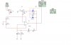
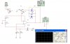
Having trouble getting a bode plot to work on my wien bridge schematic. I cant seem to work out why its not working. Ive tried various copnnections and none seem to work.

i assumed i would just put the input and out probes in the correct place and it should work, grounding the - input and ouput.

i think i am going wrong because the wien doesnt have an input signal or maybe because i need to set the circuit into oscillations before i measure?

the variable resistor needs to be about 40% to oscillate.

Can anyone help me out?

Andy

[/img]
 

Attachments

  • wien.jpg
    wien.jpg
    34.5 KB · Views: 1,966
I don't use EWB or whatever that is, but in general, you need to open the loop to do a Bode plot on an oscillator. I would break the loop between the U1 output and R5. Put your AC source between R5 and GND, and measure the output of U1, also referenced to GND. You should have slightly more than unity gain and zero phase shift at the calculated oscillation frequency if the circuit is going to oscillate.
When you do an AC simulation, which is how you get a Bode plot, all nonlinear components (diodes, in this case) are linearized to have constant parameters (R and C), independent of the instantaneous voltage across them. My point is that the diodes here will not affect the gain, which is OK, because they are just there to provide soft limiting so that the output oscillations don't saturate the amplifier.
 
Ron H said:
I don't use EWB or whatever that is, but in general, you need to open the loop to do a Bode plot on an oscillator. I would break the loop between the U1 output and R5. Put your AC source between R5 and GND, and measure the output of U1, also referenced to GND. You should have slightly more than unity gain and zero phase shift at the calculated oscillation frequency if the circuit is going to oscillate.
When you do an AC simulation, which is how you get a Bode plot, all nonlinear components (diodes, in this case) are linearized to have constant parameters (R and C), independent of the instantaneous voltage across them. My point is that the diodes here will not affect the gain, which is OK, because they are just there to provide soft limiting so that the output oscillations don't saturate the amplifier.

Hi Ron

thanks for the reply, when you say put your ac source between R5 and GNd what do you mean. Are you saying use another piece of equipment such as signal gen etc to input an external signal? I assumed i could use the bode plotter without an extra equipment since the circuit generates its own signal.

cheers

Andy
 

Attachments

  • wien2.jpg
    wien2.jpg
    54.3 KB · Views: 2,883
andy257 said:
Ron H said:
I don't use EWB or whatever that is, but in general, you need to open the loop to do a Bode plot on an oscillator. I would break the loop between the U1 output and R5. Put your AC source between R5 and GND, and measure the output of U1, also referenced to GND. You should have slightly more than unity gain and zero phase shift at the calculated oscillation frequency if the circuit is going to oscillate.
When you do an AC simulation, which is how you get a Bode plot, all nonlinear components (diodes, in this case) are linearized to have constant parameters (R and C), independent of the instantaneous voltage across them. My point is that the diodes here will not affect the gain, which is OK, because they are just there to provide soft limiting so that the output oscillations don't saturate the amplifier.

Hi Ron

thanks for the reply, when you say put your ac source between R5 and GNd what do you mean. Are you saying use another piece of equipment such as signal gen etc to input an external signal? I assumed i could use the bode plotter without an extra equipment since the circuit generates its own signal.

cheers

Andy
Does "IN" (on the Bode plotter) mean input to instrument, or input to circuit? I don't use EWB. If it means to the instrument (which makes more sense) then I think you have it connected correctly.
 
Russlk said:
You do need an external signal generator. When the circuit is oscillating, it produces a single frequency, you can't get a bode plot from that.
The Bode plotter apparently has the generator in it. He has broken the loop in the most recent schematic.
 
Status
Not open for further replies.

New Articles From Microcontroller Tips

Back
Top