Continue to Site
Follow along with the video below to see how to install our site as a web app on your home screen.
Note: This feature may not be available in some browsers.
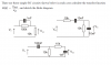
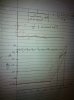
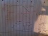
Hey guys, I have calculated the transfer function of the simple circuit attached and also drew the bode plot, can you check if its correct?
Thanks.
   0                 ------------------
                    /
                   /
                  /
                 /
 -21  -----------
0 10k 110k +infHi,
Thanks for the notes Winter.
Im adding a little note too here...
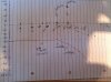
The usual procedure used is where we would divide top and bottom by R1+R2 so that we can get it into the form:
[LATEX]
.\ \ \ \ H(s)=\frac{K(s\tau_{1}+1)}{(s\tau_{2}+1)}
[/LATEX]
This is probably the form he was after for starting the problem.
Hi again,
Show us the way you would prefer to do it and we'll go from there. Be as detailed as possible showing every little step.
By 'second circuit' i assume you mean the circuit on the right, not on the bottom.
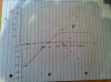
I have now also done an example myself to see if I have understood it all correctly. If we take a simple low pass filter with R = 1000Ω and C = 1μF then we have the following transfer function:
H(s) = (1/Cs) /(R+1/Cs) = 1/(RCs+1)
This transfer function is already in the correct form, but just to make sure that I follow the same steps we did before, I will change it into the following form and find the poles:
H(s) = (1/RC)*1/(s+1/RC)
We know that there is a pole at w=1/RC = 1000Hz.
From this we also get a constant of 1/RC so, 20log(1/RC) = 60dB and we get the bode plot attached.
I do wonder though, shouldn't I have had the constant when the transfer function was in its first form: H(s)= 1/(RCs+1)?
")