Continue to Site

Welcome to our site!

Electro Tech is an online community (with over 170,000 members) who enjoy talking about and building electronic circuits, projects and gadgets. To participate you need to register. Registration is free. Click here to register now.

  • Welcome to our site! Electro Tech is an online community (with over 170,000 members) who enjoy talking about and building electronic circuits, projects and gadgets. To participate you need to register. Registration is free. Click here to register now.

Board design for high current?

Status
Not open for further replies.

HellTriX

New Member
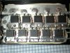
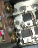
I am designing a board with 15 to 20 parallel mosfets. I need some ideas on how to design this board with the ability to flow 600-800 amps of current at 100-144 volts. I'm pretty sure no board I could etch would be able to supply even 100amps. So I'm trying to think of a way to design a board where I could bolt on a copper buss bar right next to the mosfets to carry the high current and still allow the mosfets access to the heat sink. Or solder individual large wires right near each mosfet and run those to a bus bar.

Any ideas would be helpful.

The mosfets are 200v 65amp mosfets with 15 to 20 in parallel, with a high current driver circuit and switching frequency of 25-30khz. Average load per mosfet not expected to be more then 170v at 20A, with peak of 50A for less then a few seconds happening very seldom.
 
Who says they're 65A MOSFETs? The manufacturer? Or you? If it's the manufacturer, sit down and calculate the switching and conduction losses and find out the temperature rise of the FET- it's probably a lot less than what they say it is. My 75V so-called 160A MOSFETs can only handle 10A without no heatsinking, and with passive heatsinking they can only handle 25A, and active air cooling heatsink can handle 40A- that's with 10kHz switching. Those amp ratings don't tell you much- you should manually figure it out from the RDon.

Are you sure you can switch that many paralleled MOSFETs at that frequency? It sounds like you might run into problems providing enough gate drive current (unless you already sat down and calculated those out too), or you might run into problems with getting all the FETs to turn on at around the same time. 15 FETs is a pretty long chain.

If you use FETs like this, you could just bolt the damn things onto a metal plate, and use wire and forego the PCB for all the power altogether.
<looking for the link, IRF changed added a new product and it has screwed up the link on their website, it's a big flat package with screw mounting tabs and 4 screws on top for ring terminals>
 
Last edited:
65amp at 25c
50amp at 100c

switching losses at 30khz is 3.44 watts with my current driver setup.

max package sustained load is 75Amps.
but its only thermally stable if held at 65A @ 25c.

so Im derating them to a duty cycle of about half that..
25amp at sustained load assuming 100C temps.

max dissipation around 35 watts per mosfet worse case scenario. Each mosfet peak dissipation is 380 watts.

So I think I'm well within the safe operating limits.
 
Oh and I did the calculation yesterday for switching time for the parallel chain.

It was a switching time of around 120-160nS for turn on.

I will be load balancing the gates with low value resistors to prevent oscillations and to hopefully get similar turn on rates. And good idea bout the plate. I'd only need ground and gate drive wires then.
 
, and active air cooling heatsink can handle 40A- that's with 10kHz switching. Those amp ratings don't tell you much- you should manually figure it out from the RDon.

It sounds like your driver can't supply enough peak current to get the switching losses very low?

I have been doing some testing with my 75v 210Amp mosfet and I've been able to push it to 50 amps with very little warming of the passive heatsink at 15khz.
I then found out the pins coming out of the mosfet actually melt at 75amps, so the 210 amp rating is beyond me.
 
I'd try and get a "star" arrangement to the gate of each FET from the driver. THe resistors might prevent oscillations, but the inductance of the chain (if daisy-chained) might make the MOSFETs turn on sequentially enough to overload the first MOSFET that turns on, and then you get a domino effect going on it if that one burns out. THat's pretty hard to do though on a PCB, if it's even possible. I'm still trying to find that type of package that would let you bolt everything onto a metal plate and just use wires to connect them all.

It sounds like your driver can't supply enough peak current to get the switching losses very low?

I have been doing some testing with my 75v 210Amp mosfet and I've been able to push it to 50 amps with very little warming of the passive heatsink at 15khz.
I then found out the pins coming out of the mosfet actually melt at 75amps, so the 210 amp rating is beyond me.

MY switching time is 200-300ns with a minimum thermal resistance of 5C (with an forced convection heatsink).

I also accounted for the fact that the RDon of the MOSFET is 2.5x what it is at 25C (3.8mR) when it is at 175C (10mR), according to the graphs in the datasheet and assumed ambient of 50C.
 
Last edited:
Found them. It is the SOT-227 package.

It's resistance seems to be a bit higher than some of the other FETs you can get now, but I these packages are MUCH larger with much better heatsinking and do not require a PCB which probably offsets the higher RDon and having to run such high currents on a PCB in the first place.

My really rough starter calculations indicate that you might be able to get away with just one or two in parallel rather than 15.
 

Attachments

  • 20M11JVR.pdf
    74.5 KB · Views: 321
Last edited:
Nice packaging on that diode. be nice to find those for mosfets.

I was just looking at the datasheet for a curtis motor controller that
happens to use 35 mosfets in parallel (idf640). The layout is in 2 long rows, with
a large buss for the gate drive with indivitual 75 ohm resistors at each of the mosfets gate. The rating for this controller is 400 amps, which is slightly more
than the 11amp rating at 100C of the mosfets datasheet. So their gate drive must be excellent to drive the mosfets to near max listed on the datasheet. They use a 15khz switch frequency.
Also they used the heatsink mount as the positive rail, and the pin goes through the board where it looks like another large bus is bolted to that for the ground bus.

It's giving me some good ideas.
 
Stupid edit time limit... cut me off in the middle of my editing so the post is all garbled and non-sensical.

Here it is again:
The SOT-227 package is the one I am looking for and I found a MOSFET in it that might suit you.

It's resistance seems to be a bit higher than some of the other FETs you can get now, but these packages are MUCH larger with much better heatsinking which probably offsets the higher RDon and take wires which removes the difficulty and expense of running star-routed high current traces to the MOSFETs.

My really rough starter calculations indicate that with a 1C/W heatsink, you only need ONE MOSFET. So with switching losses and higher ambient temperatures you could probably get away with paralleling just two rather than 15.
 

Attachments

  • 20M11JVR.pdf
    74.5 KB · Views: 266
Last edited:
Found them. It is the SOT-227 package.
My really rough starter calculations indicate that you might be able to get away with just one or two in parallel rather than 15.

Very nice mosfet. The only problem is. I purchased 20 of the mosfets I'd like to use for 30 bucks compared to these units which are $120 a pop lol.
**broken link removed**

The cost out weight the benefits for me I think.

Edit. The total gate charge of my 20 in parallel would be about 1120, compared to 2x of those ones you mention coming in at around 1380min.
 
Last edited:
I used 0.025 copper sheet, soldered the mosfets to it, and an electrically insulating, hard-setting, heatsink material (Loctite 383). The 10 mosfets are half-H configuration with a dedicated driver on the logic board. Peak power is around 200 A (no way to measure) at 12 V. It powers a 6V Ford long-shaft starter motor running at 12V.

John
 

Attachments

  • Power brd original4 reduced.jpg
    Power brd original4 reduced.jpg
    65.7 KB · Views: 260
  • Power end original mica reduced.jpg
    Power end original mica reduced.jpg
    52.6 KB · Views: 223
Hi to both of you,

this is just an idea, but might solve the problem concerning gate control.

dkgnyen, if you suggest just two parallel MosFets there would probably be heat problems arising.

So my idea is to arrange the transistors in a circular pattern of let's say 6, which is quite easy to have them mounted all "radiating" from the center point with the gate connections in the center of the circuit. That way they would all have equi distance from the feed point and there won't be any domino-effect derating the circuit.

I'll make different package orientations with Eagle (normally limited to 90 degrees movement) and will come up with a PCB-layout soon.

BTW, time for a new avatar, dear.

Hans
 
Are they that much? I found similar versions that are $30 each. I haven't decided if I want to use SMD ones yet or these SOT-227s yet. Right now, the cost of the required PCB seems to FAR outweight the cost of the more expensive SOT FETs. My problem isn't as easily solved as sticking them in a circle since my project has 3 phases and it's a bit hard to power route power between adjacent rings of FETs. What are you building with your FETs?

If your route requires a high current PCB, check out GOld Phoenix- about $360 for a 2-sided 6oz PCB for about 1 square foot of area (divideable into identical PCBs, or one massive one). Far cheaper than the $1000 I was quoted for at other places.

BTW, time for a new avatar, dear.
Hans

Is it that time already?
 
Last edited:
Added thought: For that type of power, why not use IGBT? I know you have the mosfets already, but they might be used for something else. I got a couple of these (cm400du-12f) for about $10 each on ebay.

John
 

Attachments

  • cm400du-12f datasheet.pdf
    82.4 KB · Views: 243
Added thought: For that type of power, why not use IGBT? I know you have the mosfets already, but they might be used for something else. I got a couple of these (cm400du-12f) for about $10 each on ebay.

John

lol Wow those are massive.

I'm building a high efficiency motor controller. My prototype uses 2x 100 amp mosfets that I ran a chevy starter motor with at 100 amps 12V.
I was going to build a simple and cheap motor controller for use on a motorcycle conversion. But I was so happy with the results of the first few tests. I decided to scale it up a bit more for converting a 280z I have laying around. **broken link removed**

I'm the do it yourself type, but I'm a bit extreme. Rather than just buy the parts and convert the car. I like to design every component and build it.
I'm self taught in everything I do. I even have a prototype electric motor I built a few weekends ago using laminated sheet metal and some windings from an old transformer. Gonna do some testing on it and maybe build a larger version for the EV conversion. I'd be happy if it happens to be more then 70% efficient hehe.

I have a company that will sponsor me enough batterys for the 280z if I can show them the completed motor controller and and nearly complete conversion.

I think all told the conversion will be under $2000. with my goal being in the $1500 or less range (including the $850 for electric motor, if my custom built one sucks).

Im actually in college studying for doctorate in physics. I haven't really taken and courses in electronics yet so my knowledge is just a lil better than amature I'd guess.
 
Added thought: For that type of power, why not use IGBT? I know you have the mosfets already, but they might be used for something else. I got a couple of these (cm400du-12f) for about $10 each on ebay.

John

I guess I didn't mention why I didn't consider IGBT.

I wanted to use mosfets since it seemed easier for me to design the gate drive for mosfets by just supplying 10-12v and making it capable of high peak currents.

Comparing to IGBT where I would need to supply voltage, current, as well as a negative voltage during turn off, and possible thermal runaway, latch up, and the limited switching rates.

I've had good experience blowing up Bi polar transistors in recent years. And I must say, I have yet to (knocks on wood) blow up any mosfets yet.
So I stick with whats been working good for me :D

Btw, I like how you did your mosfets on the metal strips. Is their a heatsink on the back side of those with insulating thermal stuff behind them?
 
Last edited:
The mosfets I plan to use are FDP61N20
61A, 200V.
Rds ON: 0.041ohm @ Vgs 10V
58nC total gate charge typical.
 
The mosfets I plan to use are FDP61N20
61A, 200V.
Rds ON: 0.041ohm @ Vgs 10V
58nC total gate charge typical.

Hi HellTriX,

I've made a package and a layout for four APT20M11JVR (SOT-227 package). Since that device has M4 screws to connect cables I don't see any problem connecting them for high current.

The board design has a trace width of 16mm. Using 70um of copper it should be able to handle high current, also because the traces are ringshaped.

The gate connections are drawn on the component side and all have equal lenght.

Boncuk
 
Last edited:
Hi HellTriX,
I've made a package and a layout for four APT20M11JVR (SOT-227 package). Since that device has M4 screws to connect cables I don't see any problem connecting them for high current.
Boncuk

This is awesome. Ty.

I will have to look around for some lower cost APT20M11JVRs.
Only seen one source so far at $120 each.

tnx again
 
Btw, I like how you did your mosfets on the metal strips. Is their a heatsink on the back side of those with insulating thermal stuff behind them?

Yes. The whole thing is mounted to a heatsink, which is the black object behind them. John
 
Status
Not open for further replies.

New Articles From Microcontroller Tips

Back
Top