Continue to Site

Welcome to our site!

Electro Tech is an online community (with over 170,000 members) who enjoy talking about and building electronic circuits, projects and gadgets. To participate you need to register. Registration is free. Click here to register now.

  • Welcome to our site! Electro Tech is an online community (with over 170,000 members) who enjoy talking about and building electronic circuits, projects and gadgets. To participate you need to register. Registration is free. Click here to register now.

Blowing 555s.

Status
Not open for further replies.

bitem2k

New Member
Hi , does anyone have any experience of 555 failure?
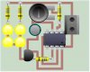
I made simple strobe light pcb, which works fine. Then suddenly after if not being switched on for a day or so, it refuses to flash, and just lights the leds constantly.

Does anyone have any ideas what might cause this?

It has happened several times with several different chips.

My power supply is 9v. Im driving 4 superbright leds at 3.8v each @20mA.
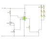
I have wired them into two series sets consisting of 2 leds and a resistor for each set, these two sets of leds are then wired up to the collector of a transistor.
I have wired pin 3 of the 555 to a resistor and the resistor to the base of a transistor which switches 40mA (two lots of series leds). I have used the transistor in case of me needing to switch heavier loads in the future.

Thanks very much.
 

Attachments

  • Strobe9V.jpg
    Strobe9V.jpg
    11.8 KB · Views: 243
  • Tracks.jpg
    Tracks.jpg
    15.8 KB · Views: 189
Yup, pin 4 should be at supply voltage. in your case 9 volts dc.
 
We cannot see all the pcb wiring underneath parts, so why not post the schematic complete with parts values?
 
Dont worry about that circuit, it doesnt matter really, but i just want to know if anyone else at somepoint has had any problems with 555s failing, and how they resolved the problem?

thanks
 
A 555 will fail if its load resistor has a value that is too low, causing an output current higher than 200mA.
There is also a limit on how low is the value of its timing resistors.
 
Here is the schematic.
I have also included the pcb layout, before it has been flipped(for toner transfer method).

Thanks
 

Attachments

  • Untitled-1.jpg
    Untitled-1.jpg
    7 KB · Views: 222
  • Untitled-2.jpg
    Untitled-2.jpg
    26.2 KB · Views: 208
It is too bad you saved the schematic as a fuzzy JPG file type instead of a very clear GIF or PNG file type because it is difficult to see the pins numbers of the IC.

Is the 100k thing a potentiometer? It should have at least 1k in series because if it is turned to zero ohms then the discharge transistor at pin 7 takes a beating discharging the capacitor as fast as it can and getting hot.
 
Sorry about my error on pin 4 not being connected. On the original attachment, that just sort of jumped out.


Question: are you using that BC337 NPN transistor in this circuit also? I want to be sure before I comment on your transistor placement this time
 
Last edited:
audioguru said:
It is too bad you saved the schematic as a fuzzy JPG file type instead of a very clear GIF or PNG file type because it is difficult to see the pins numbers of the IC.

Is the 100k thing a potentiometer? It should have at least 1k in series because if it is turned to zero ohms then the discharge transistor at pin 7 takes a beating discharging the capacitor as fast as it can and getting hot.
I was thinking about that. If I calculated it correctly, the average power dissipated in the discharge transistor at max frequency is only about 0.65mW (6.5mW if the other resistor is 1k, as in his previous schematic). I'm not sure what the high peak power will do to it. Seems to me like a resistor in series with the pot would be prudent, although the datasheet shows the monostable with no current limiter for the discharge pin.
 
Yep still BC337, Yep its a 100k pot.
So do you think that my problem is caused by low resistance when pot is turned down?

thanks very much everyone.
 
Last edited:
And nothing is getting hot at all? That would rule out shorts in soldering. I can't think of any reason why 'leaving it for a day or so' would have any effect on any of the components.

Could it be that it is flashing, just very quickly? too quickly for you to see, possibly indicating a faulty pot or a short. If you have access to any form of test equipment, een a logic probe, it might be handy for checking if its oscilatting at all, at any part of the circuit. I haven't had any probs with 555's bumming out on me, unless I accidently fed them with 12v reverse polarity.....:eek:

Blueteeth

Edit:

Just noticed, the first picture you posted, its connected up wrong, I assume this is simply an artifact of the software used to create this image, rather than the design itself, as the PCB layout you posted looks just dandy......although that is viewed from the 'component side'. So you were correct in flipping that for toner transfer....if your PCB was clear, you could see that pattern as you look through it from the non-copper side. SO....the first PCB layout (second picture, first post) should be >exactly< what you printed off for toner transfer, as its the mirrored version of the layout.
 
Last edited:
bitem2k said:
Hi , does anyone have any experience of 555 failure?
My power supply is 9v.
If you are using a wall wart AC adapter, remember that a 9V one will output considerably more than 9V when lightly loaded such as when the LEDs are in the OFF state. I think the absolute max supply voltage for a 555 is around 15V and a 9V wall warts output can come close to this if the line voltage is high in your area. Something to check.
 
No, im running of a 9v battery.
The first pic i posted, is a flipped view of the one i just recently posted. Its confusing I know, All the components on the first pic are the wrong way around, because they do not need to be flipped, as they will be on the other side of the board anyway. I just included them so you get a rough idea of whats what.

Im just going to leave the circuit on with 0 pot resistance until battery dies, and see if another chip blows.


thanks everyone for your suggestions.
 
Where's the decoupling cap?
The NE555 timer requires a decoupling capacitor to function.
You have failed to include one in your circuit.
 
Last edited:
Why not leave it on with full resistance. That's when the LEDs will blink slowest.
 
Because im trying to determin whether the 0 resistance is what is blowing the 555.

Do 555 blow without the decoupling capacitor? Im not so sure as other circuits i have made without cap have not ruined any 555s.
thanks
 
bitem2k said:
Do 555 blow without the decoupling capacitor? Im not so sure as other circuits i have made without cap have not ruined any 555s.
thanks
It won't blow without one.

If you want your circuit to work half of the time, then don't include a decoupling capacitor.

Look at these 555 timer circuits.
**broken link removed**
 
Last edited:
Status
Not open for further replies.

Latest threads

New Articles From Microcontroller Tips

Back
Top