Continue to Site

Welcome to our site!

Electro Tech is an online community (with over 170,000 members) who enjoy talking about and building electronic circuits, projects and gadgets. To participate you need to register. Registration is free. Click here to register now.

  • Welcome to our site! Electro Tech is an online community (with over 170,000 members) who enjoy talking about and building electronic circuits, projects and gadgets. To participate you need to register. Registration is free. Click here to register now.

BLDC ESC / SERVO controller

Status
Not open for further replies.

Dr_Doggy

Well-Known Member
ok, so i started this since i need to control the esc of a bldc motor (for a RC plane) , after reading up I believe i need a 1ms pulse with a 20 ms delay, then a 1.5ms pulse with a 20ms delay, then a 2ms pulse with a 20ms delay, then i need it to repeat, maybe im wrong about this?? , maybe i only need single pulse width for specific rpm??

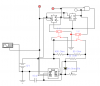
so i decided to rely on the 555 timer, in order to sequence the pulse i'v used some gates and an AND to reset it back to the first pulse width... now the simulation works great but i had to use a VOLTAGE CONTROLLED SWITCH, since i couldn't get the relay or transistors to work,..

so my other question is: is there such thing as a voltage controlled switch, what are their proper names>??

How would i replace the voltage switch with a transistor>?

also what could i do to substitute the AND gate,(i would like to avoid a using whole ic if I can)

even if this is wrong about the pulses id still like to use this configuration since I could use it as an IR encoder....?
 

Attachments

  • stepper pulses.png
    stepper pulses.png
    6.6 KB · Views: 1,122
Such a simple circuit won't work with a brushless motor (though I admit I have no idea how you're trying to achieve your goal with that circuit). But there are several reasons:

-You need to know the position of the rotor in real-time so you know when to pulse and whart part of the sequence you should be pulsing. THis requires a rotor position sensor, or more commonly a sensorless back EMF circuit to detect the rotor position.

-A single pulse width for a specific RPM only works if the load is known and constant. Heavier loads require longer pulse widths (or more speciically duty cycles) for the same RPM. If this weren't the case, you'd be able to sprint with a heavy backpack just as easily as with no backpack.

-If using a sensorless back EMF circuit, a special startup algorithm is needed since the motor must be moving for back EMF to be produced to know where the rotor is. It needs to know the rotor position to properly send commutatation pulses to turn the motor, but it needs the motor to already be spinning so BEMF Is produced so it know the rotor position! Catch 22 if the motor is starting at zero speed a microcontroller).

-There are no simple high frequency switches that you can simply plug into a circuit. You have relays but they are SLOOOOWWW and wear out fast. Transistors are used but things are more complicated since the control voltage required is referenced to one of the primary terminals. Put another way, the control pin is the gate and the primary pin in question is the source. But the required control voltage itself is the voltage between the gate-source. Since the source pin is a primary pin, it will be at whatever voltage it is while the circuit operates- you can't control it really. And since your circuits will mostly be outputting signals referenced to ground it's going to be a problem since the control voltage at the gate is being referenced to the source (which may or may not be at ground). In bidirectional motor drives, this happens. So you have additional circuitry to deal with that- so called high-side gate drivers (versus the much simpler low-side gate drives). Knowing how to use a MOSFETs as a switch is critical.

-A quick glance at your circuit also only shows logic...no power components. To drive something like a motor you need the circuit to have the smarts to know what to do and the muscle to do it. Your circuit seems to lack any muscle and that is at least half the battle. Logic circuits in rare cases might satisfy the voltage requirements for the motor, but they never satisfy the current requirements. You can't hook something like a motor directly to a something like a flip-flop, logic gate IC, microcontroller and expect that ALL that power required by the motor is going to be passed from the battery to motor through that tiny little part.

Best to go for a BLDC driver IC, or make it from scratch using a microcontroller, gate drivers, rotor sensing circuitry, and the actual drive transistors. Just know you aren't saving money the DIY route.

Read through this, of particular importance is the commutation sequence. It will also give you an idea of what the circuit needs to look like an an abstract level (just replace IGBT transistors with MOSFET transistors for your application).
https://www.electro-tech-online.com/custompdfs/2010/08/00885a.pdf
https://www.electro-tech-online.com/custompdfs/2010/08/00857a.pdf

I suggest after reading up on this, go back to the drawing board and begin designing with the power stage first, then work your way backwards to the smarts that determine the proper commutation sequence. Investigating the power stage will introduce you to things like high-side gate drives, low-side gate drives, flyback diodes, power MOSFETs, H-bridges, and half-bridges (which is realy just half an H-bridge). The power stage of a BLDC driver consists of three half-bridges, one for each phase of the BLDC. This in turn is made up of power MOSFETs and flyback diodes. It is driven from the low power, control circuitry via the gate drivers. The control circuitry is usually a microcontroller.

Using a BLDC driver IC will tend integrate the control circuitry with the gate drivers, and for the lowest power motors will also integrate the power MOSFETs.
 
Last edited:
^ I think he already has the brushless speed controller (ESC being the terminology for an Electronic Speed Control in radio control circles). RC servos (and speed controllers) use the pulse width to determine position (servo) or speed (motor controller), usually somewhere in the range of .7ms to 2.5ms depending on the system.

So why do you need to control the motor with your own circuit instead of using the output from the RC receiver? Or is this for another project that isn't radio controlled?
 
Last edited:
Ah, yeah you're right. I must have totally glossed over where he typed "esc".

THat's a much simpler circuit than he actually has then isn't it?
SERVO TESTER Circuit
 
Last edited:
Ya, , I need to control ESC ! but it has 5 input wires, power and ground (high guage) , then i got 3 data wires, i found out they were vcc ground and signal wires, but it doesnt have voltage ratings for signal, or its vcc,

yes, adamey, I am working on my own type of transmitter, actually im giving my "quad copter" independent stability controlling,
so a single pulse width will control speed in a bldc, thnx! that cleans up alot of confusion on my part, and in my timer!
 
ohya, but that leaves my other problem, i want to replace the switches in the SERVO TEST CIRCUIT, with transistors, but am having problems integrating them, that's why i am using the "VOLTAGE CONTROLLED SWITCHES" in my circuit, is there such things as these? what are they called? digi key part number?, what else could i use so that i can use parallel code to switch my 555 pulse rates?
 
Quad coptor? As in you have 4 motors and 4 sets of blades? I hope you're not planning on using the speed control for stability - that would be way too slow. Much better to use servos to control the pitch of the blades for stability as you could get very fast response on the amount of lift/thrust from the blades. Motors take time to speed up/slow down, IMO.

The 3 wires from the ESC would be 5V (or maybe 4.5V, can't remember), ground and the pulse width input. Most ESC's are used to provide power for the radio receiver and normal servos, and this is done with a BEC (battery eliminator circuit) on the ESC so you don't need a separate 4 cell battery pack for the radio electronics. You could also conventiently use these wires to provide power for your own circuit instead of making your own voltage regulator.

What are the "inputs" for your switches? From some sort of tilt sensor?
 
Quad coptor? As in you have 4 motors and 4 sets of blades? I hope you're not planning on using the speed control for stability - that would be way too slow. Much better to use servos to control the pitch of the blades for stability as you could get very fast response on the amount of lift/thrust from the blades. Motors take time to speed up/slow down, IMO.

In practice it's WAY more mechanically complicated, heavy and expensive to do that since you are basically making 4 regular helicopters. The control isn't quite as crisp if you rely on the response of electric motors and use rotor speed to control but its much lighter, simpler and reliable and that's the advantage of a quadcopter. Doing otherwise totally negates the point of a quadcopter and you might as well just build a traditional heli which would be cheaper and more reliable and have greater efficiency and higher capacity.

You tend to need PI, PD, or even PID control loops for this kind of thing though and the ability to tune the gains which means that you're best off with a microcontroller of ANY kind rather than a hard wired circuit with 555 timers and such. You can almost forget about interfacing sensors to it if you hardwire it too since sensors are analog but your circuit is digital. That means you need an ADC. An ADC means lots of interfacing logic and wide bus widths that for practical purposes you can't discretely hardwire at all. A single microcontroller would replace ALL the parts you're asking about and the parts you need but don't know it yet, except the sensors. Most importantly it also means when your design doesn't work (and it never does the first time you can try and fix it just by reprogramming rather than redesigning and rebuilding the circuit completely). Of course, this assumes that you wired up the MCU correctly. But that's much easier to do than properly designing and wiring a big complicated hard-wired circuit to do the same thing.

If you're attempting to take the laziest and easiest route, it's actually the microcontroller route, and not hardwiring the circuit. If you're low on resources and can't afford things like the hardware or software needed to program an MCU, there are solutions out there like the PICAXE (a single chip) or Arduino (a general board solution you connect your own circuits and things to and this one is used a LOT for quadcopters)
 
Last edited:
Last edited:
boo...uC idk how to use those, ima stick to the hard wire i think, but thnx for all the help!
 
In practice it's WAY more mechanically complicated, heavy and expensive to do that since you are basically making 4 regular helicopters. The control isn't quite as crisp if you rely on the response of electric motors and use rotor speed to control but its much lighter, simpler and reliable and that's the advantage of a quadcopter. Doing otherwise totally negates the point of a quadcopter and you might as well just build a traditional heli which would be cheaper and more reliable and have greater efficiency and higher capacity.

When I first saw "quadcopter" I was imagining something very large with each individual copter being the same size as a typical RC helicopter. When I googled it I realized these are actually very small, lightweight copters utilizing small motors and propellors.

In these examples, I can see where the motor speed being varied to control lift would work great and keep things nice and simple.

To the OP, I can't see any way to make one of these work without using a microcontroller. There are just so many variables to keeping the thing flying that trying to make something work with a discreet circuit would likely be almost impossible.


Unfortunately for my wife, I have found a new project I want to try and build, having a background in RC planes & helicopters and having a ton of old parts lying around....
 
im not useing a remote control, im going to wire it to follow a specific light, that s y it needs to self balance, im going to use a primary detection circuit, with a balance override circuit, and an input device to set up primary detection mode.

......that is after i get the ESC going!
 
Status
Not open for further replies.

Latest threads

New Articles From Microcontroller Tips

Back
Top