Continue to Site

Welcome to our site!

Electro Tech is an online community (with over 170,000 members) who enjoy talking about and building electronic circuits, projects and gadgets. To participate you need to register. Registration is free. Click here to register now.

  • Welcome to our site! Electro Tech is an online community (with over 170,000 members) who enjoy talking about and building electronic circuits, projects and gadgets. To participate you need to register. Registration is free. Click here to register now.

BLDC Commutate to known start position

Status
Not open for further replies.

poofjunior

New Member
Hey everyone, I'm looking at brushless dc motor control theory with the idea of building my own for position control. Here's my set of parts so far:
I'm looking at the waveforms and understanding the general idea right now. So far, here's what I've got

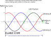
This timing_diagram picture from elabz.com shows the desired output current for a given location in electrical degrees to maximize the torque on the rotor to get it to rotate. (In reality, this pattern is repeated 7 times to get a full rotation on my three-phase motor with 7 pole pairs.) According to the application note from Microchip, "maximum torque is obtained when the permanent magnet rotor is 90 degrees away from alignment with the stator magnetic field," and I'm assuming that the timing_diagram is telling me exactly that.

I've got two questions, though:
  1. If max torque is produced by applying the appropriate waveform for the given angle in the diagram, does that waveform only apply to getting the rotor to turn in one direction? If so, do I reverse direction of the rotor by applying the inverse of the value displayed in the diagram (so as to apply the max torque in the opposite direction?)
  2. I'm using a pretty good encoder, but it's incremental. How do I commutate to a known position such that I know where I'm at to begin with?
Thanks for the hand!
 

Attachments

  • timing_diagram.png
    timing_diagram.png
    59 KB · Views: 554
  • BrushlessMotorControlMadeEasy.pdf
    393.3 KB · Views: 612
Last edited:
The permanent magnets will stop the motor in one of the poles anyway, so what's the point?

As long as the Hall sensor is not misaligned, it will start. Otherwise, failures are known to occur, especially in cheap fans, where one of the positions the fan will just dither back and forth or do nothing until assisted.

Yes 3 phases are reversed for reverse direction.
 
Last edited:
In my case, I'm actually building up the controller from scratch.

I think I may have been able to answer my questions from some reading, though.

For the first question, I should be able to just invert the values presented in the graph for the given position.

For the second question, I may be able to pick any value on the graph, and apply those current values and hold them long enough for the stator flux vector to align with the nearest pole. In this configuration, once the two vectors align, I'm getting no torque, but I now know where the rotor is relative to the stator field so that I can start the correct commutation sequence. In this case, once both vectors are aligned, I can proceed into commutation with a value (from the graph) that is 90 electrical degrees offset from the previous value that I used to align the two vectors.

I could have the wrong idea about how sensored, closed-loop, control works on these motors as I look into building my own, but let me know if this doesn't make sense.
 
For single direction single phase BLDC control , I believe the Hall sensors are positioned just before the point where torque changes direction and in some cases. factory misalignment causes a dead-spot unless nudged. For bidirectional BLDC control, one would need to switch commutation early on either side of this dead spot. Perhaps more Hall sensor hysteresis centred or two sensors... Just guessing for use without position feedback. For 3 phase bidirectional control, these issues go away as only one phase can have a dead spot.
 
Status
Not open for further replies.

New Articles From Microcontroller Tips

Back
Top