Continue to Site

Welcome to our site!

Electro Tech is an online community (with over 170,000 members) who enjoy talking about and building electronic circuits, projects and gadgets. To participate you need to register. Registration is free. Click here to register now.

  • Welcome to our site! Electro Tech is an online community (with over 170,000 members) who enjoy talking about and building electronic circuits, projects and gadgets. To participate you need to register. Registration is free. Click here to register now.

BJT H-Bridge Design Help

Status
Not open for further replies.

Chuck Visedo

New Member
hey guys:
Any transistor guns out there ??

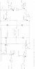
i have been trying to design a h-bridge using BJT transistors to operate a DC motor at 48 volts. The control circuit is already finished. I am using/ well plan to use, a microcontroller with pulse width modulation to control the speed of the motor. But i cant get my H-bridge to work at all! in particular i have almost no idea in working out the Resistor values of my bridge.
I have posted a picture of the design. if anyone can step me through the design process it would be much appreciated.

Heres what i have done so fare. :
given that i want to run 48 volts to the motor but which to switch it on with a 5b high from the micro controller, i have chosen 4 darlington pairs! BDX54B and BDX54C, these npn and pnp transistors have a Vceo of 80 volts! so i know they are a good choice. furthermore they have a Hfe minimum value of 750.

for the Motor that we are running i calculated the Stall current to be 10 Amps. so from this i worked out that i need ten amps in the collector of the top left transistor (on the drawing) therefore i calculated R2 to be
(48-0.4-1.7)/R2=10ma (given the Ib Ic relationship) hence R2 to be 4.6k is this right ?? if not how do i calculate the resistor values throughout the circuitry to get it to work ??

the idea is to have four output pins of the microcontroller which sends 5v high (20mA) or a 0 and in that way engage forward and revers for the motor!!

the bottom transistors i'm using are BC109s though i think there not suitable given that only have a vceo of 45

can anyone help me ??
 

Attachments

  • hbridge.jpg
    hbridge.jpg
    180 KB · Views: 705
hi,
Have a look at this method.
**broken link removed**

I would suggest that you cross link the drive transistors
ie: top left darlington with the bottom right darlington, likewise the top right and bottom left and electronically interlock the two motor drive paths so that they cannot be turned on at the same time.

In your present configuration an accidental condition could arise where the top right and bottom right darlingtons could be ON, causing a short the darlingtons. As could the other pair.!

The added advantage it requires only two PIC pins not 4.

Does this help.?:)
Google for BJT H Bridge circuits
 
thanks for the link. I sort of get what your saying but i can eliminate that condition from the micro that supplies the 5v switching on voltage. but i'm more looking to understand how so set up the system. because obviously choosing random resistor values wont work and i'm getting lost :( i just cant get them to switch. SO i want to be able to theoretically prove that this design could work! thanks very much for the link though.

can anyone help me theoretically prove this ?? is there a way of modeling this on p spice ?
 
hi chuck,
Look at this modified drawing, why do you think the 'green ringed' transistor is required.?

Does this help.?

the idea is to have four output pins of the microcontroller which sends 5v high (20mA) or a 0 and in that way engage forward and revers for the motor!!

This is not a correct statement, the PIC can supply a current of upto 20mA into a load from the 5V ideal output.
So the minimum load resistor to 0Volts, on a pin should be <= 250R

EDITED:
Corrected the location of the right hand side 2N2222 text.
 
Last edited:
thanks for the help:

I though i would need another switching transistor to turn the NPN in the green ring on, at the same time that i turn the top right hand corner on ?
the 2n2222 npn will that be strong enough ? it says that the Vceo is only 30, now I'm using 48V so i think i wont lose 18 volts in my system so the voltage could blow this transistor ?

also how can the Collector current of the 2n2222 be the same as the base current at R3, from the micro controller?

the green ring
i thought i needed to switch on the darlington NPN in order to get hte system to work ?? like send a signal from themicro to pin one and pin 4 ?? is that wrong ?
 
Chuck Visedo said:
thanks for the help:

I though i would need another switching transistor to turn the NPN in the green ring on, at the same time that i turn the top right hand corner on ?
the 2n2222 npn will that be strong enough ? it says that the Vceo is only 30, now I'm using 48V so i think i wont lose 18 volts in my system so the voltage could blow this transistor ?
Look at the ZTX [651 or 653] series of medium power transistors.

also how can the Collector current of the 2n2222 be the same as the base current at R3, from the micro controller?
They are not the same, R11 with the BC109 emitter follower is 190R and R11 is 220R direct from the PIC..

the green ring
i thought i needed to switch on the darlington NPN in order to get hte system to work ?? like send a signal from themicro to pin one and pin 4 ?? is that wrong ?
The darlington only requires about 15mA, this will switch ON the darlington, the PIC can output 20mA.

hi,
Do you follow the rest of the explanation.OK.?
 
eric:
thanks for your help, i'm still trying to get this Bridge working though. testimony to the fact that i am still lost when it comes to BjTs

to clarify something , the green ring shown on the bottom right hand side, a modification you showed. The reason i was using two transistors, the Darlington and the switching transsitor was because i was worried that the full 48 volts would interfere with the Micro (pic) and blow the pic ? is this right ? because i see you have connected the Micro directly to the Darlington?
and one i have one side working (because im bread boarding it tonight) is it safe to assume that the inverse condition will have the same resistor values right..? cheers eric
 
Chuck Visedo said:
eric:
to clarify something , the green ring shown on the bottom right hand side, a modification you showed.
The reason i was using two transistors, the Darlington and the switching transsitor was because i was worried that the full 48 volts would interfere with the Micro (pic) and blow the pic ? is this right ?
The PIC pin never 'sees' the 48V's on the BJT collector.
The forward Base to emitter voltage drop across a single transistor is only 0.7V, for a Darlington its about 1.4V.

because i see you have connected the Micro directly to the Darlington?
Via that base to PIC pin resistor.!
and one i have one side working (because im bread boarding it tonight) is it safe to assume that the inverse condition will have the same resistor values right..?
Thats correct, I have only shown one diagonal of the HBridge, they are identical.
cheers eric

Hi,
I hope this explains it OK, if not please ask.;)
 
Progress thanks to Eric !

here are some questions attached to the diagram.

also should i think about modeling this on pspice first to see if it works ? is that possible ?

and, can i control forward and reverse by sending highs to pins 1 and 4, and 2 and 3 respectively? thats the idea right ?
 

Attachments

  • questions.GIF
    questions.GIF
    350.1 KB · Views: 771
Chuck Visedo said:
here are some questions attached to the diagram.

also should i think about modeling this on pspice first to see if it works ? is that possible ?
I dont use Pspice, I'm sure someone will tell you.

and, can i control forward and reverse by sending highs to pins 1 and 4, and 2 and 3 respectively? thats the idea right ?

You have to switch ON the top left and bottom right at the same time for one direction and the top right and bottom left for the other direction.
NEVER both diagonal BJT pairs at the same time or you blow the BJTs


hi,
Do you follow.
I did say earlier you should electronically interlock the BJT's so that the incorrect paths thru the BJT's cannot happen..

EDIT: R6 and R12 should be about 4K7 to 10K.
 
Last edited:
Chuck Visedo said:
ok great.
do i need that extra transistor? in the ring ? or should i hook it up straight to the micro ?

No,,,, Yes

via the base resistor.
 
GOT it working!

thanks very much for your help ERIC!

I changed the design significantly! modifying the power supply to 36 volts,
i will post the complete design with calculations soon! But it works perfectly! even with the PWM!
 
Chuck Visedo said:
thanks very much for your help ERIC!

I changed the design significantly! modifying the power supply to 36 volts,
i will post the complete design with calculations soon! But it works perfectly! even with the PWM!

Excellent, look forward to your project posting...:D

Are you going to join in the forum competition..
 
Status
Not open for further replies.

New Articles From Microcontroller Tips

Back
Top