Continue to Site

Welcome to our site!

Electro Tech is an online community (with over 170,000 members) who enjoy talking about and building electronic circuits, projects and gadgets. To participate you need to register. Registration is free. Click here to register now.

  • Welcome to our site! Electro Tech is an online community (with over 170,000 members) who enjoy talking about and building electronic circuits, projects and gadgets. To participate you need to register. Registration is free. Click here to register now.

BJT Amplifier?

Status
Not open for further replies.

LiquidOrb24

New Member
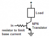
I'm working with a PSOC microprocessor and the output voltage on each line is roughly 3.1 volts. I however need alot more power to control the output devices I have.

I was originally planning on using a relay to go to another power source but then I remember in one of my classes they said we can use BJT's or MOSFET's to amplify the voltage either with a differential amplifier or some other one.

I messed around with a few schematics in multisim but cant get a nice amplification from 3.1v to around 10?

Is there anyone who can help me out with my problem or tell me if I should use a differential amlifier, Common source, Common drain or any other type of way of doing this.

Thank you all.
 
You didn't say how much current the load takes. A single transistor can switch on a load of about 250mA. A darlington transistor can switch a few amps.

You say the 3.1V must be amplified to 10V?
No. The 3.1V turns on the transistor and the load is connected to 10V.
 

Attachments

  • transistor driver.PNG
    transistor driver.PNG
    3.3 KB · Views: 177
The 3.1 is going from the PSOC output pin with about 4mA and I would like it to power several LED's and maybe some sensors that take in about 5V and 20-50mA each (proabably around 2 sensors) So I would need the Vcc of the transistor to be connected to possibly a 9 volt power supply, or an RC car battery at about the same voltage, to somehow give out 5-10 volts to the load from either the collector side, or if I'm using a difference amplifier to use the difference to power the load.
 
I really suck at Transistors so I'm wondering in that schematic you posted are you saying to use the transistor as a switch rather than as an amplifier?

Thank you by the way for that Shematic I think I might be making this too complex.
 
The base voltage of the transistor is about 0.7V when it is turned on, so the resistor will have 3.1V - 0.7V= 2.4V across it. With 4mA through it, then the resistor value is 2.4V/4mA= 600 ohms. Use 620 ohms which is the closest standard value.

Most transistors turn on very well when their collector current is 20 times the base voltage, so any little transistor can be used and the load current can be 4mA x 20= 80mA. A darlington power transistor can be used instead to switch much more current.

Any little transistor or darlington transistor is rated for more than 9V.

You don't need a differential nor amplification. You just need a transistor to turn on and off.
 
Thank you very much for the help...If theres one thing I need to learn more its the opperation of the transistor seeing how its used for almost everything.

I changed my circuit schematic to that simple layout and things are working perfectly. I got the right amount of voltage coming out of the collector side with a 9 volt battery connected to Vcc. Now all I have to do is order a few of those Darlington transistors and I'm in buisness.

Once again thank you very much... And I hope that spam doesn't follow you around... I sure as hell never seen it as a reply before.
 
I have seen many 5V relays but thier coil draws a lot of current. I haven't seen a 3V relay and it would draw even more current for its coil.
 
Status
Not open for further replies.

New Articles From Microcontroller Tips

Back
Top