Continue to Site

Welcome to our site!

Electro Tech is an online community (with over 170,000 members) who enjoy talking about and building electronic circuits, projects and gadgets. To participate you need to register. Registration is free. Click here to register now.

  • Welcome to our site! Electro Tech is an online community (with over 170,000 members) who enjoy talking about and building electronic circuits, projects and gadgets. To participate you need to register. Registration is free. Click here to register now.

BJT Amplifier design

Status
Not open for further replies.

phoenixy

New Member
I have to build an amplifier that have the following spec

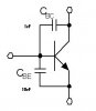
1. Use two BJT blocks(attached)
2. signal source is sin voltage with 10K source resistance. Output is 100mV peak-to-peak sin with any DC offset. Midband voltage gain should be more than 10. Output load is a 1k resistor
3. Power supply: up to +15 and -15
4. The important part of the amplifier is that it should maximize gain bandwidth product
5. Of course, I can add as many resistors/cap as I want.
The BJT I use are Fairchild's 2N3904 IC.

What design should I use?

Currently, I'm thinking about a common-base - common-emmiter cascode.

*Edit: in the previous diagram, the unit for the capacitors had been mistakenly change from nF to uF
 

Attachments

  • trans_568.jpg
    trans_568.jpg
    6.2 KB · Views: 1,374
I would expect Cbc and Cbe to be in pF not uF.

Have you searched this site for "amplifier"

Also try web sites such as www.discovercircuit.com

Have you studied amplifier design? Your knowledge appears to be very basic.

Len
 
Hi phoenixy,

Homework assignment?

I would point you to an excellent site where you can learn all you need to complete your assignment.

**broken link removed**
 
phoenixy said:
Cbe and Cbc are in uF range. It's part of the requirement.

I'm studying amplifier design. This is a lab assignment.

If you fitted those value capacitors across the transistor you wouldn't have much of an amplifier - if you don't know that then perhaps you shouldn't be doing the course?.

As 'ljcox' suggested they are going to be in pF and the internal capacitance of the transistor, NOT added external components.

As you suggested, a cascode configuration can give high bandwidth and good gain, but it's output impedance is usually fairly high.
 
The transistor circuit diagram you are showing appears to be an extremely unusual circuit, especially when using capacitors in microfarads.

I think I read from Harry's homebrew that "Amplifiers oscillate" and "oscillators amplify".

To be simple, the output must be constantly on and off, not always in one state, or you will have a basic switch. I find that a large capacitor between base and collector can make things 100% worse because you will have to depend on the transistor to slow it's speed down greatly, and it wont want to do that.

Let me explain how I think it could work with a capacitor and an NPN:

1. A signal is injected into the input (-ve).
2. The output is +ve.
3. The capacitor gets charged
4. When the input signal is inverted, the output will remain +ve because the capacitor is holding the +ve charge.

now if we replaced the capacitor with a resistor, then we have action like so:

1. A signal is injected into the input (-ve).
2. The output is +ve.
3. The +ve signal is directly injected back to input through the resistor, forcing it to be +ve.
4. The output is now -ve, and the -ve signal is fed back to input through the resistor.
5. The process repeats.

The operations mentioned above are altered if a constant +ve signal is injected into the input.

I like capacitors from emitter to ground. I think they can be great signal extenders, because whatever +ve signal is applied to the input is applied to the capacitor. When the input drops, it does not drop immediately. Instead, it drops slowly, depending on the capacitor.
 
Dear god !!!! those stray cap value better be in pF!!!! or nF at a push!!!!

the Base capacitor will basically slow down how long it takes to start teh BJT conducting, in this case ~0.6!!!!, not as much a problem as it is for FET's

Equally the Collector-Base capacitor is known as the Millar capacitor and it basically will oppose what you try to do to the base (w.r.t. the collector potoential) equally it is usually this stray that causes BJT's to oscillate if they are not setup correctly.


The only place you are likely to see value with this order of magnitude are in Power BJT's where they switch at a maximum speed of 1kHz for amperages in the order of 1000A and higher. THese are only switched in and out of saturation, you try to use these as an analogue amplifier at their rating they will blow and quickly!!!


please confirm those strays
 
phoenixy has already said that he is doing a lab assignment. so there is no point in telling that the capacitors should be in the pF range. he must have studied that in his course. but in the lab you have to experiment with such experiments. this is how you learn a thing from practicing it.

this is a part of the learning process. his teacher would have told him that stray capacitances are a disaster for amplifier design. but this lab assignment will be a proof of that statement. seeing is believing! so if you havent seen it you wont believe it.

just my two cents!
 
I get 19 dB gain and 3kHz bandwidth. If you can do as well, your instructor will be impressed.

To maximize bandwidth, you need to minimize the voltage variation across the capacitors. Common base configuration is good for that.

The cascode gives me 25.7 dB gain and 3.7 kHz bandwidth, good choice!
 
Status
Not open for further replies.

Latest threads

New Articles From Microcontroller Tips

Back
Top